When a pipeline engineer specifies a 24-inch diameter carbon steel elbow for a high-pressure offshore platform, or an aerospace fabricator needs a tight-radius titanium tube routed through a confined airframe cavity, one decision shapes everything downstream: which bending method to use. Induction bending and mandrel bending represent two distinct approaches to precision tube bending, each with clear advantages, limitations, and application sweet spots. Choosing incorrectly means scrapped material, failed qualification tests, or costly rework.
This guide breaks down both methods with the technical depth production planners and engineering managers need to make confident, application-specific decisions in 2026.
How Induction Bending Works
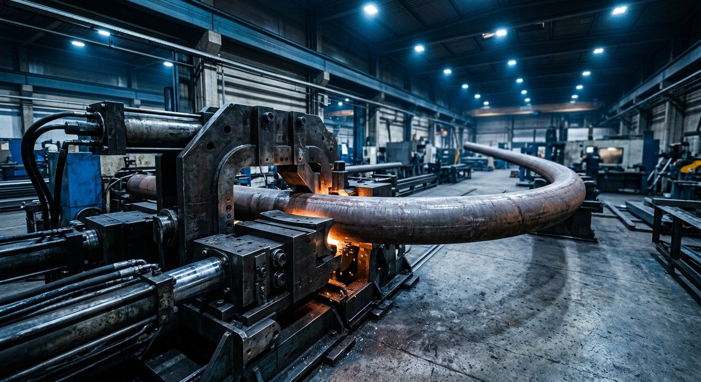
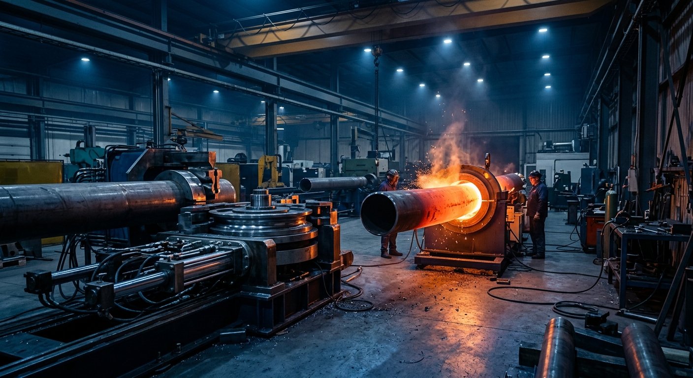
Induction bending uses a localized electromagnetic heating coil to heat a narrow band of pipe or tube—typically one to three pipe diameters wide—to a controlled temperature range, often between 850°C and 1100°C for carbon steel. As the pipe passes through the coil at a controlled feed rate, a pivot arm applies bending force to the heated zone. The material bends at the heated band, then immediately quenches through water cooling as it exits the coil.
This continuous, incremental process means large-diameter industrial pipe benders can produce long-radius bends in heavy-wall pipe without the need for internal tooling. Induction bending is the dominant method for large-diameter pipeline elbows in the oil & gas and petrochemical sectors, where pipe diameters can range from 4 inches to 60 inches or more.
Strengths of Induction Bending
- Large diameter capability: Handles pipe sizes impractical for mechanical bending equipment
- Long-radius bends: Typically produces bends with a centerline radius of 3D to 7D or greater
- Minimal tooling contact: No internal mandrel required, reducing tooling costs on heavy pipe
- Wall thickness retention: Controlled heating minimizes thinning on the extrados
- Material versatility: Suitable for carbon steel, stainless steel, chrome-moly alloys, and duplex materials
Limitations of Induction Bending
- Post-bend heat treatment is often required to restore mechanical properties altered by the induction process
- Not suitable for tight-radius bends (typically below 3D)
- Less effective for small-diameter tubing where localized heating control becomes difficult
- Equipment and setup costs are significant; induction bending is primarily economical for large-diameter, heavy-wall applications
According to the American Society of Mechanical Engineers (ASME), pipe bends in pressure piping systems must meet specific dimensional and material property requirements under standards such as ASME B31.3, making post-bend qualification a critical step in induction bending workflows.
How Mandrel Bending Works
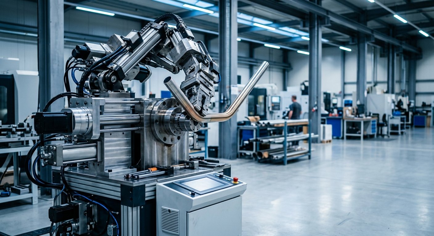
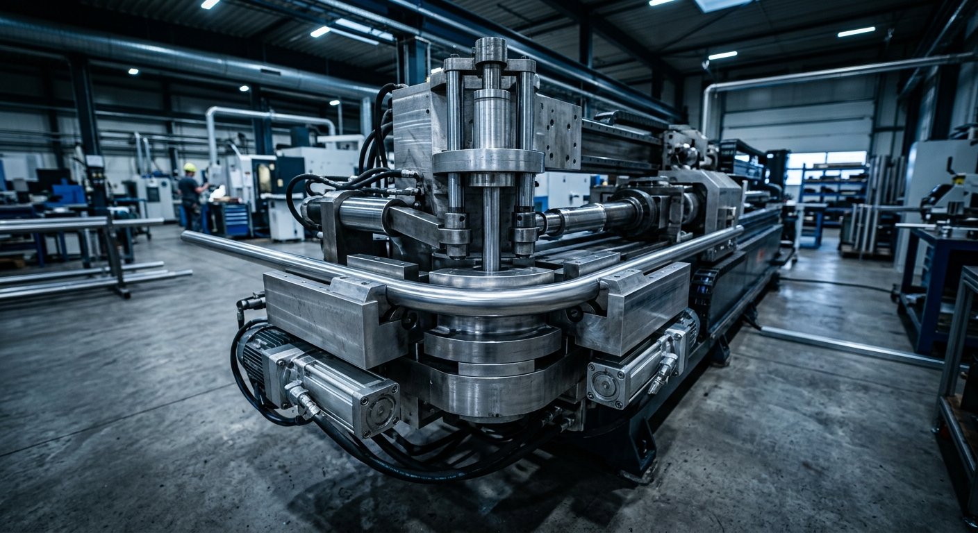
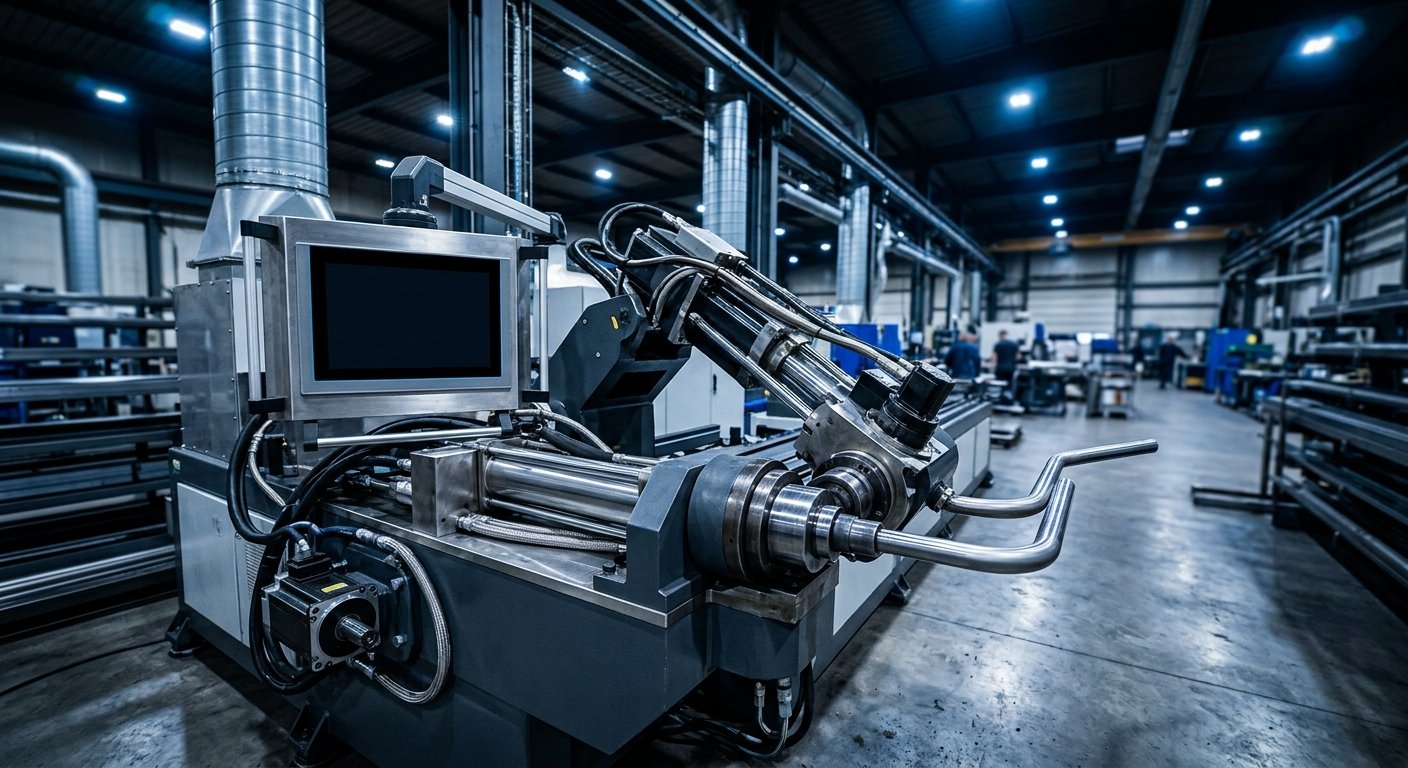
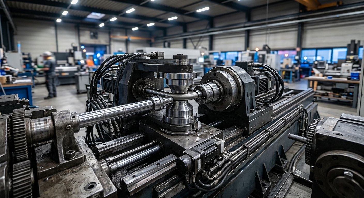
Mandrel bending is a cold-forming process in which a tube is bent around a fixed bend die while an internal mandrel—a precision-machined plug or ball assembly—supports the tube wall from the inside. A pressure die stabilizes the straight portion of the tube while a wiper die prevents wrinkling at the intrados. The result is a bend with tight dimensional tolerances, minimal ovality, and excellent surface finish.
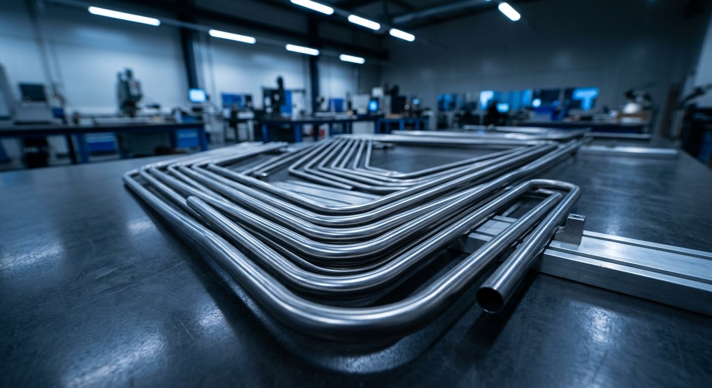
This method is the foundation of precision tube bending across aerospace, defense, automotive, and high-purity process industries. CNC tube benders executing mandrel bending can produce complex, multi-plane bend geometries in a single setup, making them indispensable for high-volume production and exacting dimensional requirements.
Strengths of Mandrel Bending
- Tight radii: Capable of bend-to-diameter ratios as tight as 1D or even less on specialized tooling
- High dimensional accuracy: CNC tube benders with mandrel tooling routinely achieve repeatable tolerances critical to aerospace and defense applications
- No heat input: Preserves base material mechanical properties without post-bend heat treatment in most applications
- Complex geometries: Multi-axis CNC systems can execute compound bend sequences in a single automated cycle
- Small to medium diameters: Optimal for tubing typically ranging from 0.25 inches up to 6 inches or more depending on the machine
Limitations of Mandrel Bending
- Tooling (mandrel, bend die, wiper die) must be precisely matched to tube diameter, wall thickness, and bend radius
- Very large diameter or heavy-wall pipe becomes impractical without industrial-scale equipment
- Hard materials with low elongation require careful parameter development to prevent cracking
For aerospace applications, precision tube bending per NASA standards demands tight control over springback, wall thinning, and ovality—requirements that mandrel bending with calibrated CNC tube benders consistently meets when the process is properly engineered.
Side-by-Side Comparison: Key Decision Factors
Understanding where each method excels helps engineers and procurement specialists specify the right equipment or process from the start.
| Factor | Induction Bending | Mandrel Bending |
|---|---|---|
| Pipe/Tube Diameter | 4″ – 60″+ typical | 0.25″ – 6″+ typical |
| Bend Radius | 3D – 7D or greater | 1D – 3D or tighter |
| Heat Input | Yes (elevated temperature) | Cold process (no heat) |
| Post-Bend Treatment | Often required | Rarely required |
| CNC Integration | Feed rate and angle control | Full multi-axis CNC |
| Primary Industries | Oil & gas, petrochemical, energy | Aerospace, defense, automotive |
Application-Specific Guidance
Oil & Gas and Petrochemical
Large-diameter pipeline systems and refinery process piping are where induction bending earns its place. The ability to bend heavy-wall pipe in pressure-rated alloys without internal tooling makes induction the practical choice for mainline pipe bends, offshore riser systems, and refinery interconnects. However, for instrument tubing, hydraulic control lines, and small-bore process connections throughout these same facilities, mandrel bending on precision tube bending machines delivers the tight tolerances and repeatability that fluid system integrity demands.
Aerospace and Defense
Tight-radius, multi-plane tube routing in fuel systems, hydraulic lines, environmental control systems, and structural airframe components is the domain of mandrel bending on CNC tube benders. Material traceability, dimensional conformance, and process repeatability are non-negotiable. Hines Bending Systems has supplied precision bending equipment trusted by NASA and military organizations precisely because these environments demand equipment that performs consistently under rigorous qualification requirements.
Energy and Power Generation
Both methods appear in power generation infrastructure. Induction bending serves large-diameter steam and process piping in conventional and nuclear power plants. Mandrel bending addresses smaller instrumentation and control tubing. For facilities requiring industrial pipe benders capable of handling both scenarios, equipment selection should be driven by the dominant pipe size range in the application portfolio.
The Role of CNC Technology in 2026
Modern CNC tube benders have substantially advanced mandrel bending capability. Servo-electric drive systems provide superior repeatability and energy efficiency compared to older hydraulic designs. Real-time springback compensation algorithms—built into contemporary CNC control platforms—automatically adjust bend angles based on material feedback, reducing setup scrap. Multi-stack tooling heads allow diameter and radius changes without full retooling, supporting flexible production environments.
On the induction side, digital control of coil temperature, feed rate, and cooling parameters has improved bend consistency and reduced operator variability. Both technologies continue to evolve, but the fundamental process physics that determine which method suits a given application remain unchanged.
For operations requiring true production flexibility across multiple tube sizes and geometries, custom bending solutions engineered around specific part families offer the most efficient path to quality and throughput.
Frequently Asked Questions
What is the main difference between induction bending and mandrel bending?
Induction bending uses localized heat to form large-diameter, long-radius bends in heavy pipe without internal tooling. Mandrel bending is a cold process using an internal mandrel to support tube walls during tight-radius bending, offering high dimensional precision for smaller-diameter tubing in aerospace, defense, and similar applications.
Which method is better for aerospace tube bending?
Mandrel bending on CNC tube benders is the standard for aerospace applications. It delivers the tight radii, dimensional accuracy, and multi-plane bend capability required for fuel, hydraulic, and environmental control tubing without heat input that could alter material properties.
Can induction bending achieve tight radii?
Induction bending is optimized for long-radius bends—typically 3D centerline radius or greater. It is not suited for tight-radius applications where 1D or 2D bends are required. For tight radii, mandrel bending equipment is the appropriate process.
Do mandrel-bent tubes require post-bend heat treatment?
In most applications, mandrel bending is a cold process that preserves base material mechanical properties without requiring post-bend heat treatment. Certain highly work-hardened or stress-sensitive alloys may require stress relief, but this is material-dependent rather than a standard process requirement.
How do I select the right tube bending technology for my application?
Key decision factors include tube or pipe diameter, required bend radius, material type, dimensional tolerances, production volume, and applicable industry standards. A qualified bending equipment manufacturer with application engineering expertise—like Hines Bending Systems—can evaluate your specific requirements and recommend the appropriate process and equipment configuration.
Choose the Right Method for Your Application
Both induction bending and mandrel bending are proven, essential technologies in industrial precision tube bending. Neither replaces the other. The right choice depends entirely on your pipe diameter, bend geometry, material requirements, and quality standards. Getting this decision right from the outset eliminates costly process development cycles and protects qualification timelines.
With 50 years of tube and pipe bending expertise and American-manufactured equipment trusted by NASA and military clients, Hines Bending Systems helps engineers and production managers specify the right solution the first time. Whether you need a production-volume CNC tube bender for aerospace tubing or a custom solution for demanding industrial pipe bending requirements, our application engineering team is ready to work through the details with you.
Contact Hines Bending Systems today to discuss your application requirements and get expert guidance on selecting the tube bending technology that fits your production goals.