Aerospace tube bending demands strict adherence to dimensional tolerances, material properties, and bend geometry specifications that directly affect structural integrity and fluid system performance. Engineers must understand wall thinning limits, centerline radius ratios, ovality tolerances, and material-specific springback behavior before specifying equipment or approving a bending process for flight-critical components.
- Wall thinning must stay within acceptable limits—typically defined by the governing specification—to maintain pressure ratings and structural integrity.
- Centerline radius (CLR) to tube diameter ratio governs bend difficulty and mandrel requirements; tighter ratios demand more precise tooling.
- Ovality and springback are material-dependent variables that must be characterized and compensated for in the bending program.
- Aerospace-grade alloys like titanium, Inconel, and 21-6-9 stainless each present distinct bending challenges that require matched machine capability.
- CNC tube benders with closed-loop feedback are the current standard for repeatable, traceable aerospace bending operations.
Why Aerospace Tube Bending Has Zero Tolerance for Guesswork
Fluid systems in aircraft and spacecraft carry hydraulic pressure, fuel, oxygen, and environmental control media—often simultaneously and under extreme thermal cycling. A bent tube that falls outside dimensional specification does not just fail a quality check; it can contribute to system failure at altitude or in orbit. That reality elevates precision tube bending from a manufacturing step to a safety-critical operation governed by FAA Advisory Circular 43.13-1B, customer design specifications, and, where applicable, military standards such as MIL-HDBK-5 for metallic materials.
The demands placed on tube form—straightness, bend angle accuracy, end-to-end length, and surface condition—are specified on engineering drawings with tolerances that leave little margin. Achieving those tolerances consistently, across production runs and across materials with variable temper and lot-to-lot chemistry, is what separates precision bending equipment from general-purpose shop tooling.
Mandrel selection is one of the most consequential tooling decisions in aerospace bending. The wrong mandrel type—or worn mandrel balls—allows the tube ID to collapse during the bend, causing internal cross-section loss that no external inspection will catch. Always verify mandrel withdrawal timing against the tube OD and wall thickness specification.
The Four Dimensional Specifications That Drive Every Bend Decision
1. Centerline Radius to Diameter Ratio (CLR/D)
The ratio of the bend’s centerline radius to the tube outside diameter is the primary variable that determines difficulty. A 2D bend—where the centerline radius equals twice the tube OD—requires substantially more tooling support than a 5D bend. Aerospace hydraulic lines frequently specify 2D or 2.5D bends to save envelope space. Below 1.5D, most materials require specialized tooling and a thorough process qualification. Engineers specifying tight-radius bends should confirm that the bending machine and tooling set are rated for the specific CLR/D and wall thickness combination.
2. Wall Thinning
The outer wall of a tube stretches during bending, reducing wall thickness. The amount of thinning is a function of CLR/D ratio and the tube’s original wall thickness. Most aerospace specifications set a maximum allowable wall thinning percentage—often in the range of 20–25 percent of nominal wall thickness—that must not be exceeded. Mandrel bending machines support the tube ID to limit collapse and redistribute thinning, but tooling setup and lubrication directly influence the actual thinning achieved. Process engineers should measure wall thickness at the extrados of every first-article bend using ultrasonic testing.
3. Ovality
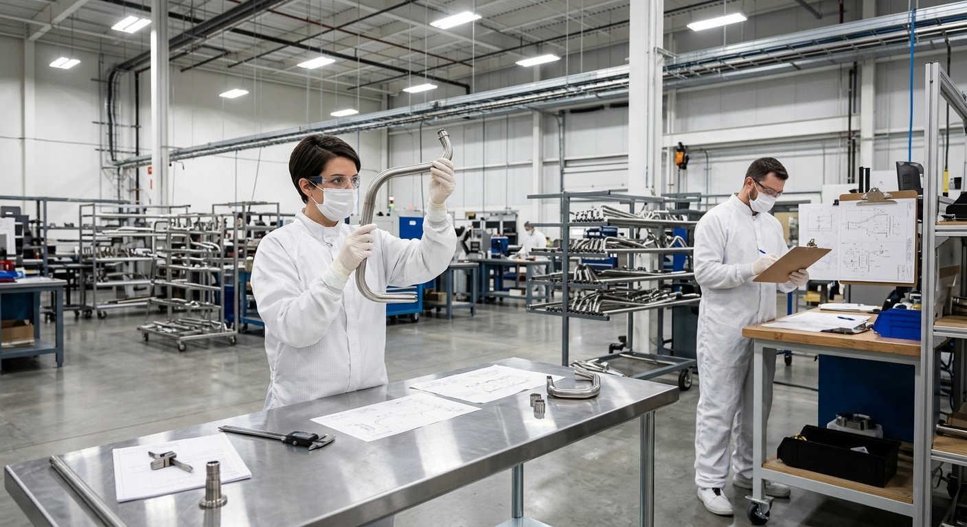
Ovality, the deviation of the tube cross-section from a perfect circle at the bend, affects flow coefficient in fluid lines and fit-up clearance in structural assemblies. ASTM standards for tube products define roundness tolerances for the straight tube, but bending introduces additional out-of-round condition that must be separately controlled. Wiper dies and correctly positioned mandrels are the primary controls. Measuring ovality with a pin gauge or digital ID gauge at multiple points through the bend confirms process compliance.
4. Springback and Angle Accuracy
All metals spring back after the bending load is released. Springback magnitude is material-dependent—titanium springs back significantly more than annealed aluminum, and Inconel behaves differently than 304 stainless. CNC tube benders equipped with angle-measuring feedback compensate for springback automatically, but the compensation factor must be established through first-article testing for each material lot and temper. Drawing-specified bend angles in aerospace applications are almost always the final angle after springback, not the overbend angle applied during forming.
| Specification | What Controls It | Primary Measurement Method |
|---|---|---|
| CLR/D Ratio | Bend die radius, machine capability | Coordinate measuring machine (CMM) |
| Wall Thinning | Mandrel type, lubrication, feed speed | Ultrasonic wall thickness gauge |
| Ovality | Wiper die, mandrel position | Digital ID gauge or pin gauge |
| Bend Angle | CNC program springback compensation | CMM or optical angle measurement |
Aerospace Alloys and Their Bending Characteristics
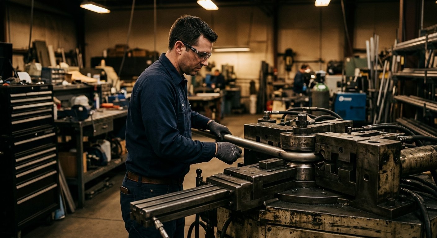
Material selection drives equipment requirements. Each aerospace alloy family presents a distinct combination of strength, ductility, work-hardening rate, and springback that must be matched to the bending machine’s capability and tooling design.
- Titanium (Ti-3Al-2.5V, Ti-6Al-4V): High strength-to-weight ratio and corrosion resistance make titanium the standard for hydraulic tubing on modern aircraft. Its high springback and sensitivity to surface damage require CNC mandrel bending machines with precise control and corrosion-resistant tooling. Some alloys require hot bending above certain wall thickness thresholds.
- 21-6-9 Stainless Steel: Widely specified for aircraft hydraulic and pneumatic lines, this nitrogen-strengthened austenitic alloy work-hardens rapidly. Bending must be performed in the annealed condition, and tooling loads are significantly higher than for 304 or 316 stainless.
- Inconel 625 and 718: Used in engine and exhaust systems where high-temperature performance is required, these nickel superalloys demand high forming forces and robust tooling. Heat treatment after bending is often required to relieve residual stress.
- Aluminum (6061-T0, 3003-O): Common in low-pressure systems and environmental control ducting, aluminum bends readily in annealed temper. Age hardening after forming can restore strength to near-T6 properties.
Material selection drives equipment requirements—matching the alloy’s springback, work-hardening rate, and surface sensitivity to the right bending machine capability is what makes aerospace precision achievable.
CNC Tube Benders in Aerospace Production
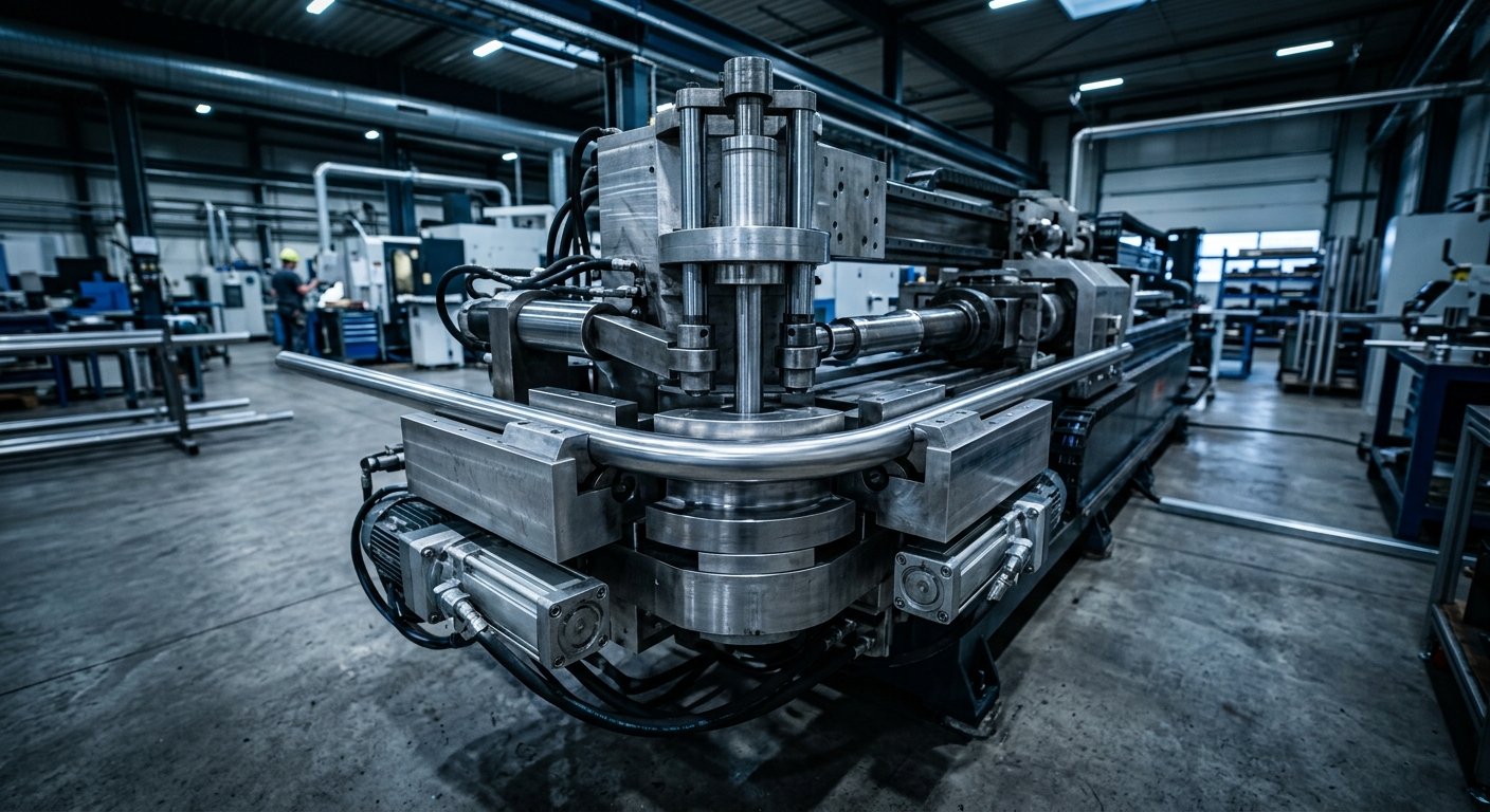
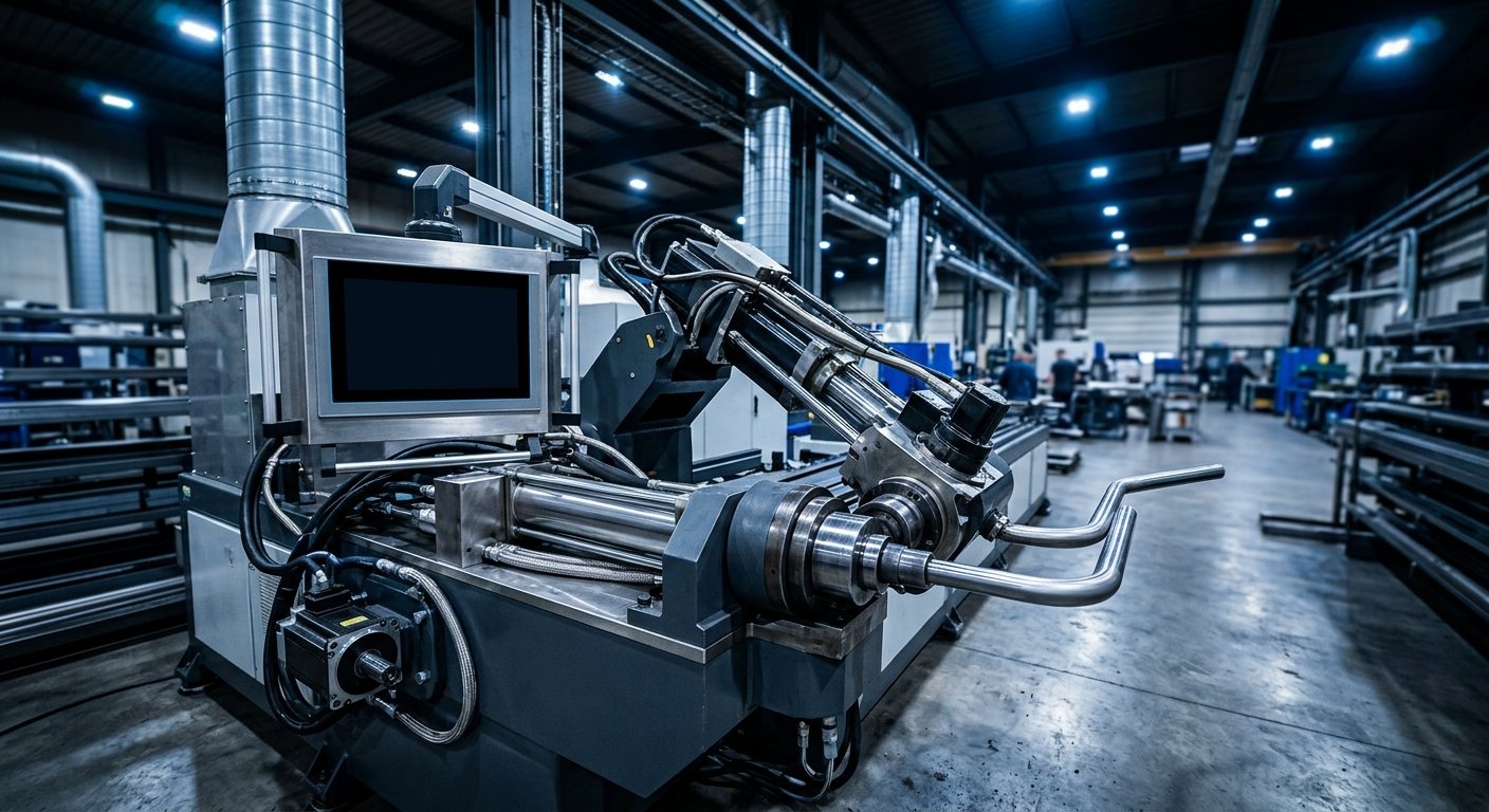
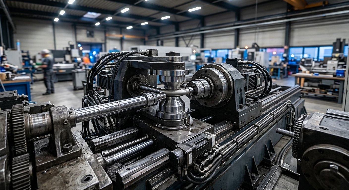
Modern aerospace production relies on CNC tube benders for repeatability, traceability, and the ability to store and recall validated bending programs. Multi-axis CNC machines can execute compound bends—multiple bends in multiple planes on a single tube—with consistent angular and positional accuracy that manual or semi-automatic equipment cannot achieve at production volumes.
Closed-loop feedback systems on current-generation machines monitor bend angle in real time and apply springback correction without operator intervention. This capability is essential when bending titanium or Inconel, where springback can vary with material lot. Program traceability—recording bend parameters, machine settings, and operator ID for each part—supports the documentation requirements of AS9100 quality management systems, the standard governing aerospace manufacturing quality.
For shops supplying aerospace tube bending applications, the machine’s control system must be capable of storing qualified programs and flagging deviations from set parameters. This is not a convenience feature—it is a quality system requirement for most aerospace customers.
At Hines Bending Systems, our tube bending machines and pipe bending machines are designed and built in America with the precision and repeatability that aerospace and defense customers require. With 50 years of industry experience and a proven track record supplying NASA and military programs, Hines engineers understand the documentation, tooling, and machine capability demands that flight-critical applications impose.
When qualifying a new aerospace tube bending process, run first-article bends across the full range of expected material lots—not just a single piece of tubing. Springback compensation factors can shift meaningfully between lots of the same alloy and heat treatment, particularly with titanium. Build that variability into your qualification test matrix.
Tooling Quality and Maintenance in Aerospace Bending
Tooling condition has a direct and measurable effect on dimensional output. Worn bend dies produce overbent or inconsistently formed parts. Worn mandrel balls allow tube ID collapse. Wiper die edges that are chipped or improperly set cause wall wrinkling at the intrados. In aerospace applications, tooling maintenance is not optional—it is part of the process control plan.
Tooling should be dimensionally verified at defined intervals or after a defined number of cycles. Replacement criteria should be established during process qualification, not left to operator judgment. This discipline—engineering the maintenance cycle rather than reacting to failures—is what keeps process capability indices at levels that satisfy aerospace customer audits.
Frequently Asked Questions
What is the minimum CLR/D ratio achievable in aerospace tube bending?
Most aerospace applications specify 2D or greater to balance packaging constraints with forming feasibility. Some specialized fittings and structural applications require 1.5D bends, which are achievable with the right mandrel bending machine, tooling, and material condition, but require thorough process qualification and increased inspection requirements. Below 1.5D is considered non-standard and demands case-by-case engineering review.
How does AS9100 certification affect tube bending operations?
AS9100 is the quality management standard for the aviation, space, and defense industries. It requires documented process controls, traceability of materials and process parameters, first-article inspection records, and controlled maintenance of tooling and equipment. CNC tube bending programs must be revision-controlled, and any change to a qualified process requires re-validation. Suppliers to aerospace primes are typically required to hold AS9100 certification or operate under a quality plan that meets its requirements.
When is mandrel bending required versus rotary draw bending without a mandrel?
Mandrel bending is required whenever the bend geometry, material, or wall thickness would otherwise result in unacceptable cross-section collapse or ovality. For most aerospace hydraulic and structural tubing—particularly at 2D to 3D CLR ratios—a mandrel is standard practice. Thin-wall tubing almost always requires a mandrel. Heavier-wall tube at large CLR/D ratios may be bent without a mandrel, but this must be verified through first-article inspection against the applicable specification.
What traceability documentation is typically required for aerospace bent tube?
Aerospace customers typically require material certifications (heat and lot traceability), dimensional inspection reports for each part or per sampling plan, records of the bending machine settings and program used, operator identification, and non-destructive inspection results where specified. Post-bend processes such as heat treatment or surface treatment must also be documented with certifications from the performing facility.
Can the same bending equipment handle both titanium and aluminum aerospace tubing?
Yes, with appropriate tooling changes and program adjustments. Modern CNC tube benders store separate programs for each material and part number, with springback compensation and bend speed settings optimized for each alloy. Tooling—bend dies, clamp dies, pressure dies, and mandrel assemblies—must be matched to the tube OD and CLR for each job. Changing between titanium and aluminum jobs requires a tooling changeover and verification of the correct program before production begins.
Talk to an Aerospace Bending Specialist
Hines Bending Systems engineers are ready to review your tube specifications, material requirements, and production volume to recommend the right precision bending solution for your aerospace application.

About Hines Bending Systems
Hines Bending Systems is a leading American manufacturer of precision tube and pipe bending equipment serving aerospace, energy, oil & gas, petrochemical, and defense industries. With 50 years of proven expertise and a track record of supplying NASA and military clients, Hines delivers custom bending solutions for demanding applications ranging from high-volume production to specialized one-off projects. The company combines deep technical knowledge with comprehensive support including training and service, positioning itself as a partner in customer success rather than just an equipment supplier. Visit hinesbending.com →