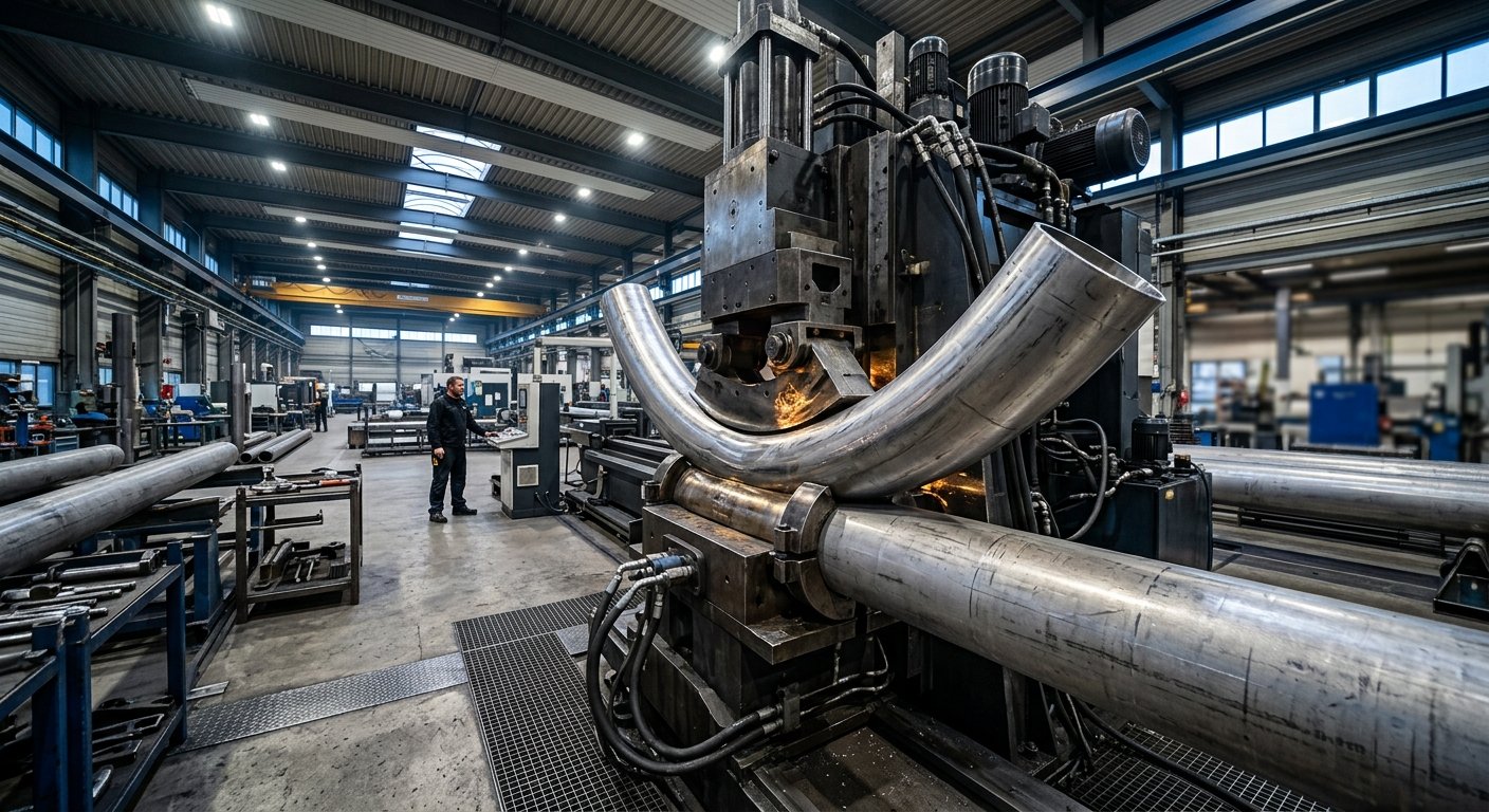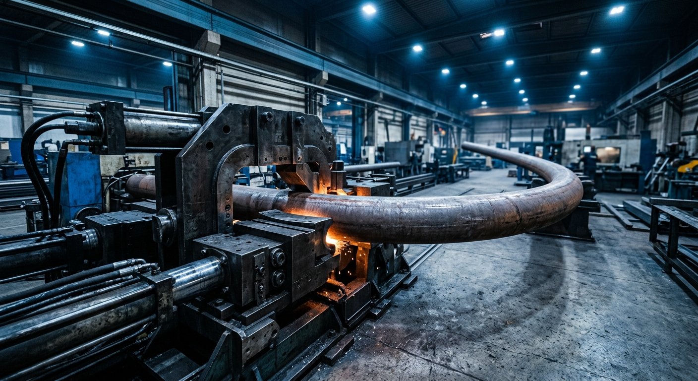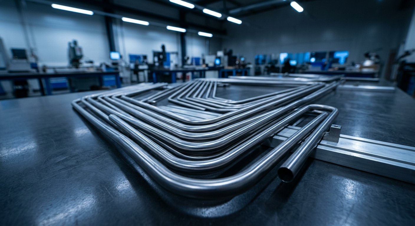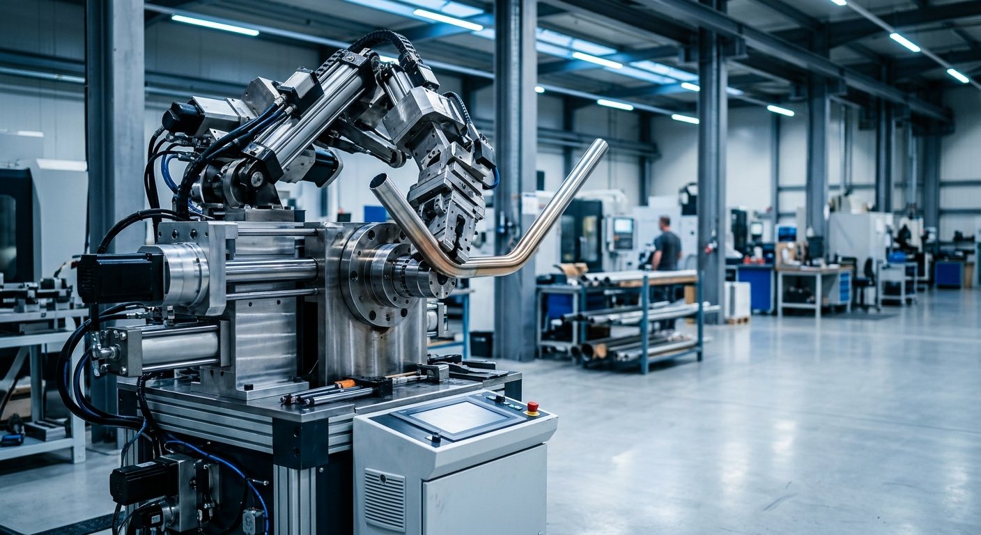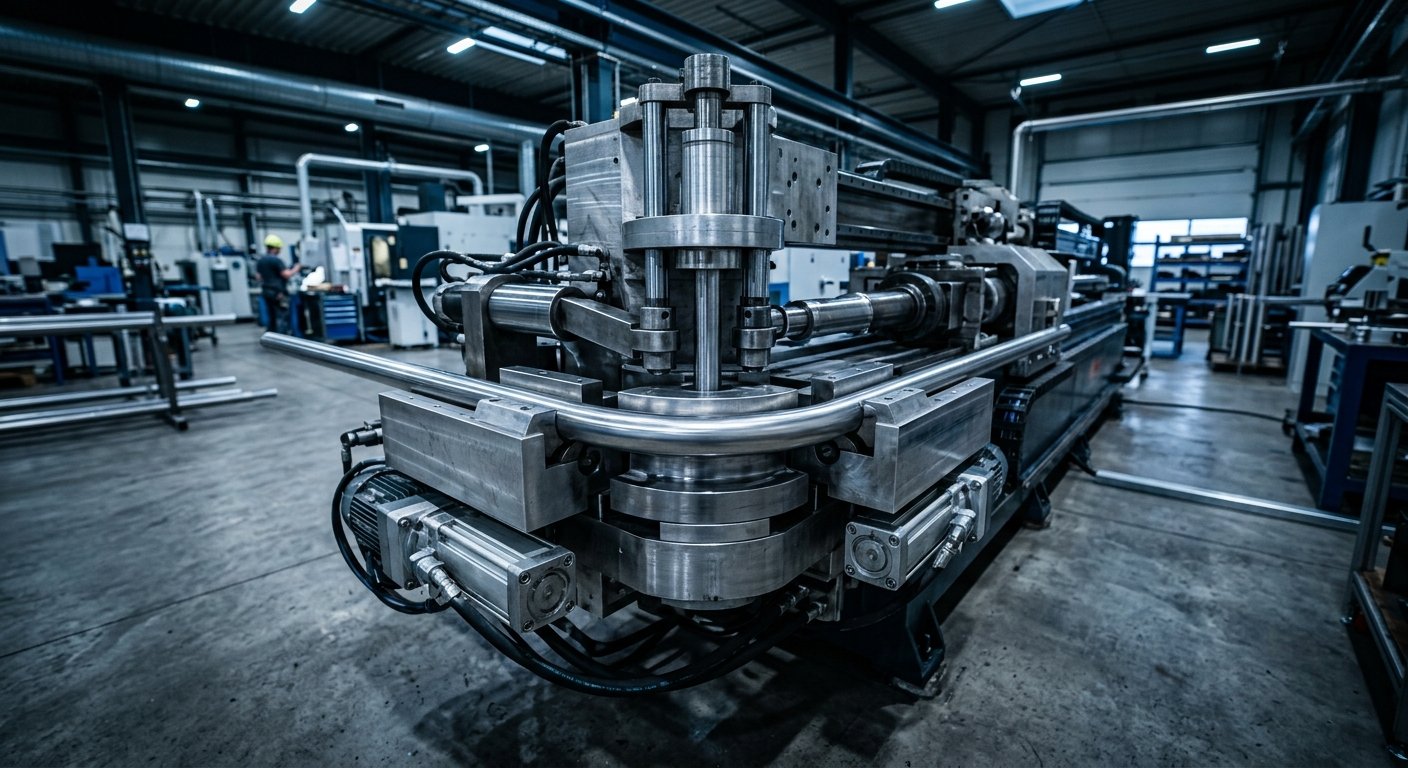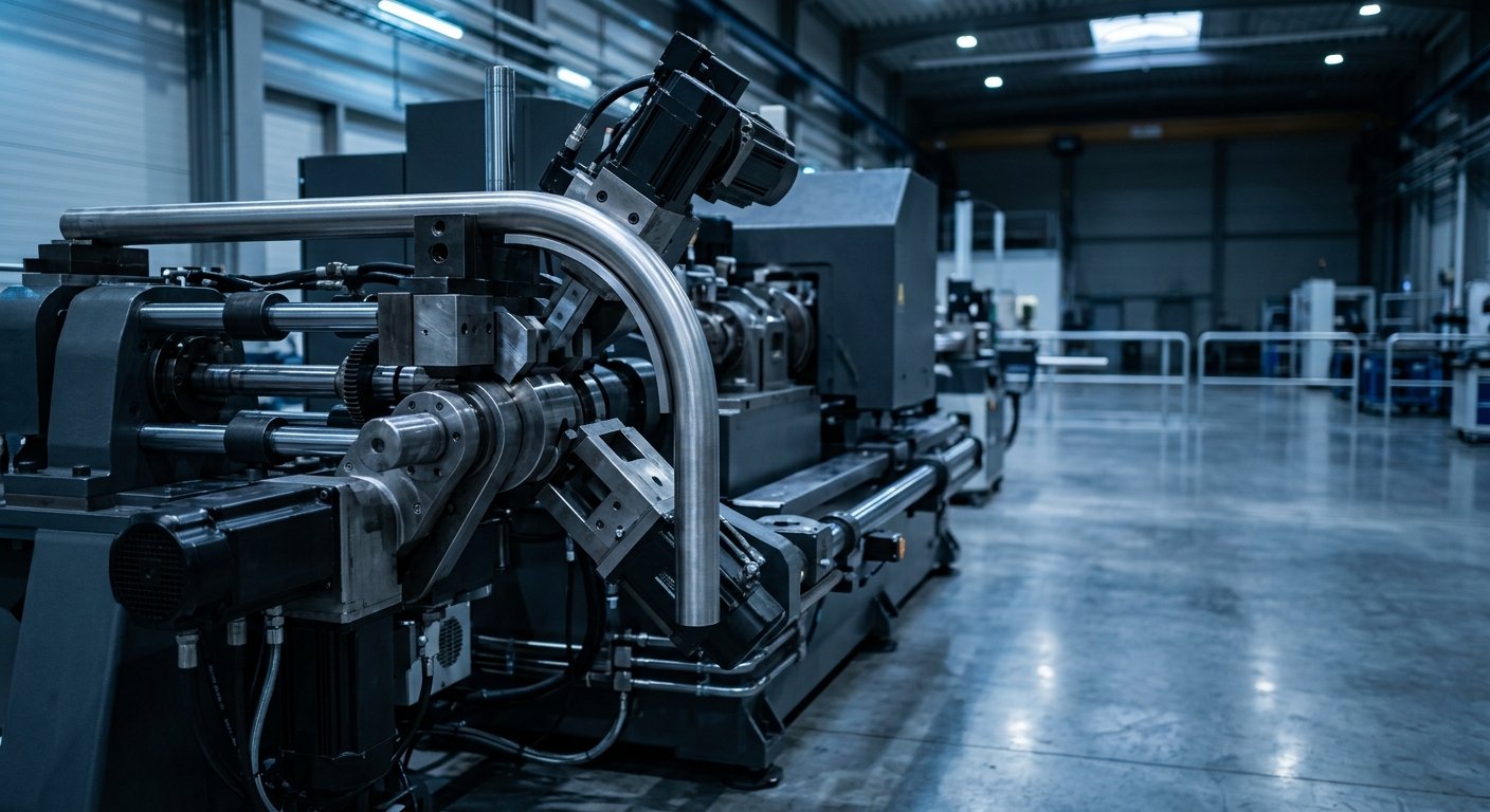
CNC tube benders handle tight-radius bends by combining precise servo-controlled motion with specialized tooling—primarily mandrels, wiper dies, and pressure dies—that support the tube wall from the inside out during deformation. This prevents collapse, wrinkling, and ovalization that would otherwise occur when the bend radius approaches or falls below the tube’s outer diameter. The result is a dimensionally accurate bend suitable for aerospace, oil & gas, petrochemical, and defense applications.
- Tight-radius bending requires internal mandrel support to prevent tube wall collapse and ovalization.
- CNC control synchronizes multiple tooling axes to maintain consistent clamp force, feed rate, and boost pressure throughout every bend.
- Material properties—wall thickness, yield strength, and elongation—determine which mandrel type and tooling geometry are appropriate.
- Proper tooling setup, including mandrel ball count and nose position, is the most critical variable in tight-radius success.
- Aerospace and defense applications often demand radii as tight as 1×D, requiring highly engineered machine-and-tooling combinations.
What “Tight Radius” Actually Means in Tube Bending
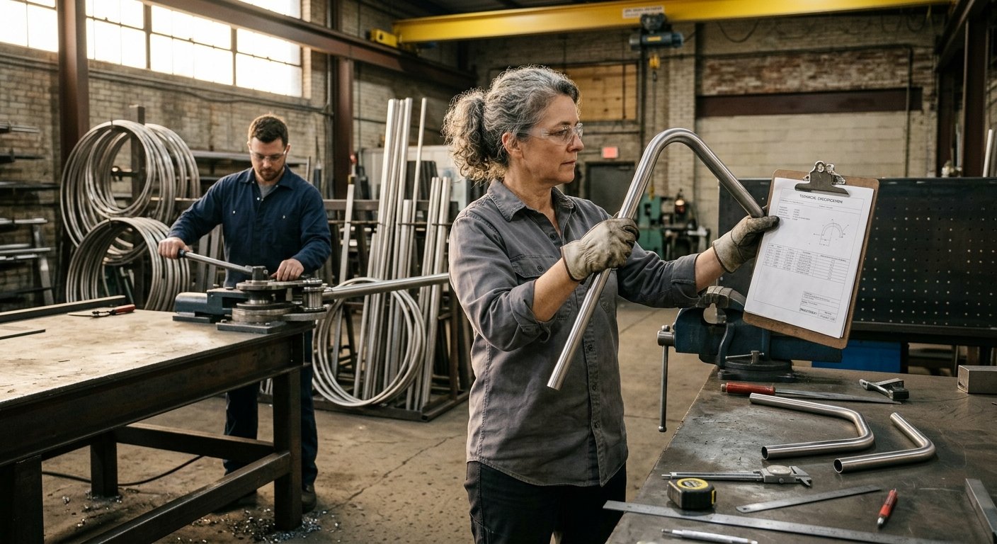
In tube bending, bend radius is expressed as a multiple of the tube’s outer diameter (OD). A 2×D radius means the centerline radius of the bend equals twice the tube’s OD. Anything at or below 1.5×D is generally considered tight-radius territory; at 1×D—where the centerline radius equals the tube OD—the geometry pushes material to its physical limits. At these ratios, the outer wall must stretch significantly while the inner wall compresses, creating conditions that challenge even robust tooling systems.
The ASME B16.49 standard for piping bends and related fabrication codes define minimum bend radii and wall thinning tolerances for pressure-service applications—a critical reference for engineers specifying bends in oil & gas and petrochemical pipework. For aerospace, FAA Advisory Circular AC 43.13-1B provides accepted practices for aircraft tubing fabrication, including bend radius requirements tied to tubing OD and material type.
Why Tight-Radius Bends Fail Without Proper Tooling
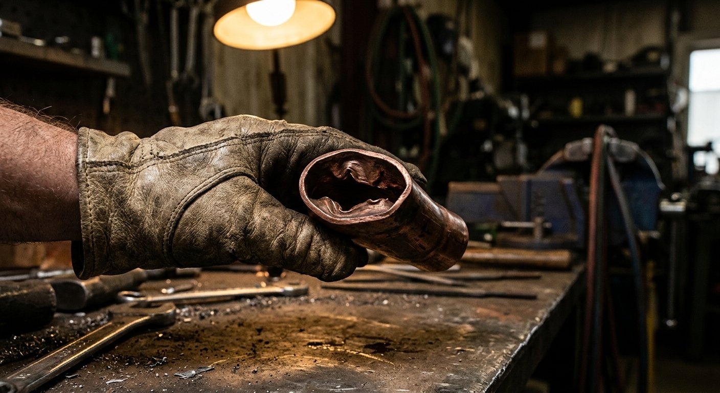
When a tube is bent without internal support, the unsupported outer wall thins and can crack, while the inner wall buckles inward, producing a wrinkle. At tight radii, these failure modes intensify dramatically. The three primary failure types are:
- Ovalization: The round cross-section deforms into an oval, reducing flow capacity and creating stress concentration points.
- Wall thinning and cracking: Excessive tensile stress on the outer wall reduces wall thickness beyond allowable limits, sometimes causing fracture.
- Inner wall wrinkling: Compressive stress on the intrados causes the material to fold, which is structurally unacceptable in pressure or fluid-carrying applications.
CNC tube benders address all three failure modes simultaneously through coordinated tooling motion and precise control over every parameter in the bending cycle.
Wall factor (OD ÷ wall thickness) is a primary indicator of bend difficulty. Tubes with a high wall factor—thin walls relative to diameter—are significantly more susceptible to collapse and wrinkling at tight radii, requiring more aggressive mandrel support and often a multi-ball mandrel assembly.
How CNC Control Changes the Equation
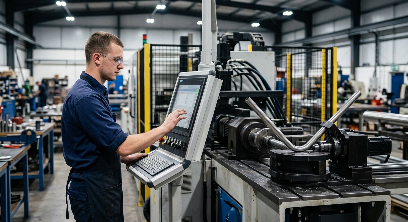
Legacy mechanical tube benders relied on fixed cam profiles and manual adjustments, making repeatable tight-radius bends difficult to achieve across a production run. Modern CNC tube benders replace mechanical linkages with servo-driven axes, each independently programmable and monitored in real time. This matters for tight-radius work in several ways:
Synchronized Multi-Axis Motion
A tight-radius bend requires the pressure die to advance (“boost”) forward as the bend arm rotates, maintaining constant contact with the tube and reducing tensile stress on the outer wall. CNC systems calculate and execute this boost profile precisely—adjusting velocity and force throughout the bend arc rather than applying a fixed mechanical push. The clamp die, pressure die, and mandrel rod can all be controlled independently, allowing the machine to respond to material springback and variations in tube hardness in real time.
Repeatability Across Long Production Runs
For production environments running hundreds or thousands of identical components—common in aerospace tube assemblies or downhole oil & gas equipment—CNC tube benders store complete bend programs including all axis positions, feed rates, and boost values. Every part is bent to the same parameters, reducing scrap and inspection burden. This repeatability is especially valuable for aerospace tube bending where part qualification can require extensive documentation of process parameters.
Adaptive Control and Springback Compensation
All metals spring back after bending—the elastic component of strain recovers when the forming load is removed. At tight radii with high-strength alloys common in defense and aerospace (Inconel, titanium, 15-5 PH stainless), springback is substantial and inconsistent between material heats. Advanced CNC systems incorporate springback compensation algorithms that overbend by a calculated angle, so the part lands at the correct geometry after elastic recovery. Some systems measure the actual springback of a sample bend and automatically adjust the program.
At tight radii with high-strength alloys, springback compensation isn’t optional—it’s what separates a production-ready program from a prototype guess.
The Role of Mandrel Tooling in Tight-Radius Success
The mandrel is the internal support tool that travels inside the tube and positions its nose at the tangent point of the bend. For tight-radius work, mandrel selection and positioning are the most consequential tooling decisions an engineer will make. The main mandrel types used in tight-radius applications are:
| Mandrel Type | Best Application | Tight-Radius Suitability |
|---|---|---|
| Plug mandrel | Large-radius, heavy-wall tube | Low — no articulation |
| Ball mandrel (single) | Moderate radii, standard wall | Moderate |
| Multi-ball mandrel | Tight radii, thin-wall tube | High — articulated support into bend zone |
| Sand/compound fill | Complex geometries, prototyping | Moderate — batch process only |
Multi-ball mandrels use a series of linked ball segments that articulate as the bend arm rotates, extending internal support further into the deformation zone. For 1×D and 1.5×D bends in thin-wall tubing—particularly the hydraulic and fuel lines common in aerospace assemblies—a correctly sized multi-ball mandrel is typically essential. The mandrel nose position relative to the bend tangent point must be adjusted to within fractions of a millimeter; too far forward and the mandrel digs into the tube, too far back and the unsupported zone collapses.
Wiper dies, positioned at the intrados immediately behind the mandrel, prevent the inner wall from wrinkling by providing a hard surface against which the compressing material is supported. For very tight radii, the wiper die tip geometry must be precision-matched to the tube OD and the bend die groove profile. Explore the full range of machine and tooling configurations available through our tube bending machines page.
Lubrication is often overlooked in tight-radius troubleshooting. Mandrel lubrication reduces friction between the mandrel balls and the tube’s inner surface, lowering the extraction force and reducing the risk of mandrel-induced scratching or tube wall damage—both unacceptable in aerospace and high-pressure service applications.
Material Considerations for Tight-Radius Bending
Material selection profoundly affects how a tube behaves at tight radii. Elongation percentage is the primary indicator of bendability—materials with higher elongation tolerate the extreme outer-wall stretch of tight-radius bends more reliably. Stainless steel grades like 304 and 316 offer good elongation and are common in petrochemical tubing. Titanium alloys used in aerospace present higher yield strengths with lower elongation, demanding careful process design. Work-hardened or cold-drawn tubing can be significantly less forgiving than annealed material at the same nominal specification.
For defense and aerospace programs where Hines has supplied precision bending equipment trusted by NASA and military organizations, material traceability and controlled processing are non-negotiable. The CNC program parameters established for one certified material heat may require adjustment for the next, making adaptive CNC control capabilities particularly valuable in these environments.
Frequently Asked Questions
What is the tightest radius a CNC tube bender can achieve?
Most production CNC tube benders can achieve centerline radii as tight as 1×D (where the centerline radius equals the tube OD) with appropriate mandrel tooling and machine configuration. Achieving radii below 1×D typically requires specialized equipment, compound bending techniques, or alternative forming processes. The practical limit depends on tube material, wall thickness, and OD.
How does mandrel bending differ from rotary draw bending at tight radii?
Rotary draw bending is the process; mandrel bending describes the tooling used within that process. In rotary draw bending, the tube is clamped to a rotating bend die and drawn around it. Adding a mandrel—internal support tooling—is what makes tight-radius rotary draw bending viable. Without a mandrel, rotary draw bending is limited to moderate radii in heavier-wall tube.
Can tight-radius bends meet aerospace quality standards?
Yes, with the correct equipment and process controls. Aerospace programs typically specify dimensional tolerances, ovality limits, and wall thinning maximums that can be consistently met on precision CNC bending equipment when tooling is properly engineered and processes are documented. FAA and NADCAP audit requirements drive the need for detailed process records and qualified operators.
When should I consider used CNC bending equipment for tight-radius applications?
Certified pre-owned CNC tube benders can be a cost-effective path to tight-radius capability, provided the machine’s servo systems, mandrel rod mechanism, and boost cylinder are in good working order. Machines with worn pressure die carriages or degraded servo drives will struggle to maintain the precise multi-axis synchronization tight-radius work demands. Our used equipment inventory is inspected and supported with full service documentation.
What information do I need to specify a CNC tube bender for tight-radius production?
At minimum: tube OD range, wall thickness range, material types and temper, minimum bend radius required, production volume (parts per shift), and any applicable industry standards or customer quality requirements. With 50 years of tube and pipe bending expertise, Hines application engineers use this information to recommend the right machine platform and tooling package for the application.
Selecting the Right Machine for Demanding Applications
Not every CNC tube bender is engineered for tight-radius production. The machine’s boost system must have sufficient force capacity, the mandrel extraction mechanism must handle the increased pull-out loads generated at tight radii, and the control system must support the multi-axis synchronization profiles tight bends require. Single-stack versus multi-stack tooling capacity, maximum CLR range, and the availability of pressure die assist are all specification items that affect tight-radius performance.
American-manufactured precision bending equipment built to handle demanding applications—from aerospace hydraulic lines to subsea oil & gas tubing—requires engineering depth that goes beyond catalog selection. The right partner brings application-specific knowledge to every machine specification, ensuring the equipment configuration matches the actual production challenge rather than a generic use case.
Talk to a Precision Bending Specialist
Whether you’re specifying new equipment for a tight-radius application or troubleshooting an existing process, Hines Bending Systems brings 50 years of expertise to the conversation—contact us to discuss your application requirements.

About Hines Bending Systems
Hines Bending Systems is a leading American manufacturer of precision tube and pipe bending equipment serving aerospace, energy, oil & gas, petrochemical, and defense industries. With 50 years of proven expertise and a track record of supplying NASA and military clients, Hines delivers custom bending solutions for demanding applications ranging from high-volume production to specialized one-off projects. The company combines deep technical knowledge with comprehensive support including training and service, positioning itself as a partner in customer success rather than just an equipment supplier. Visit hinesbending.com →