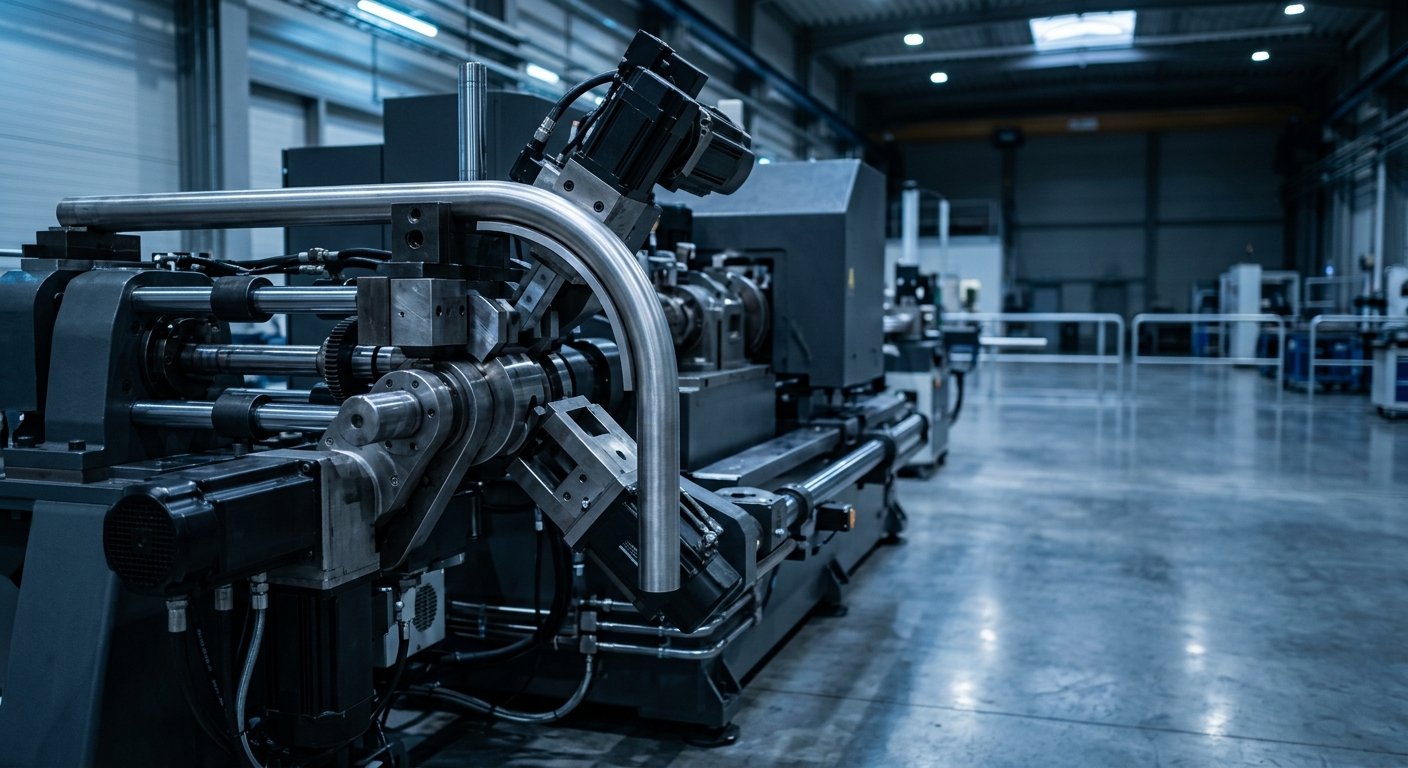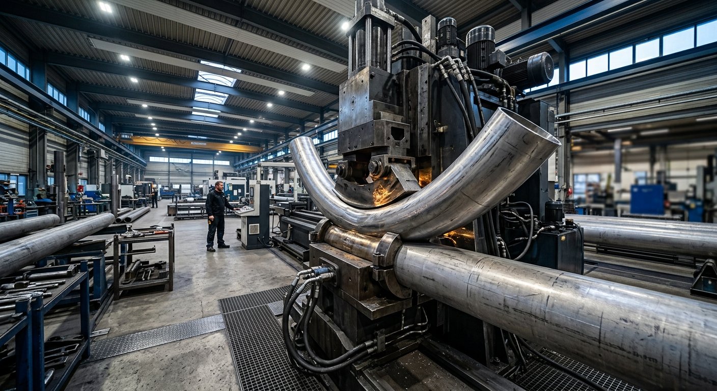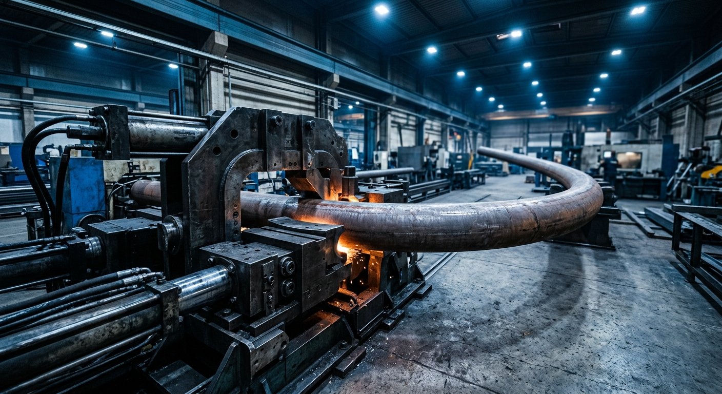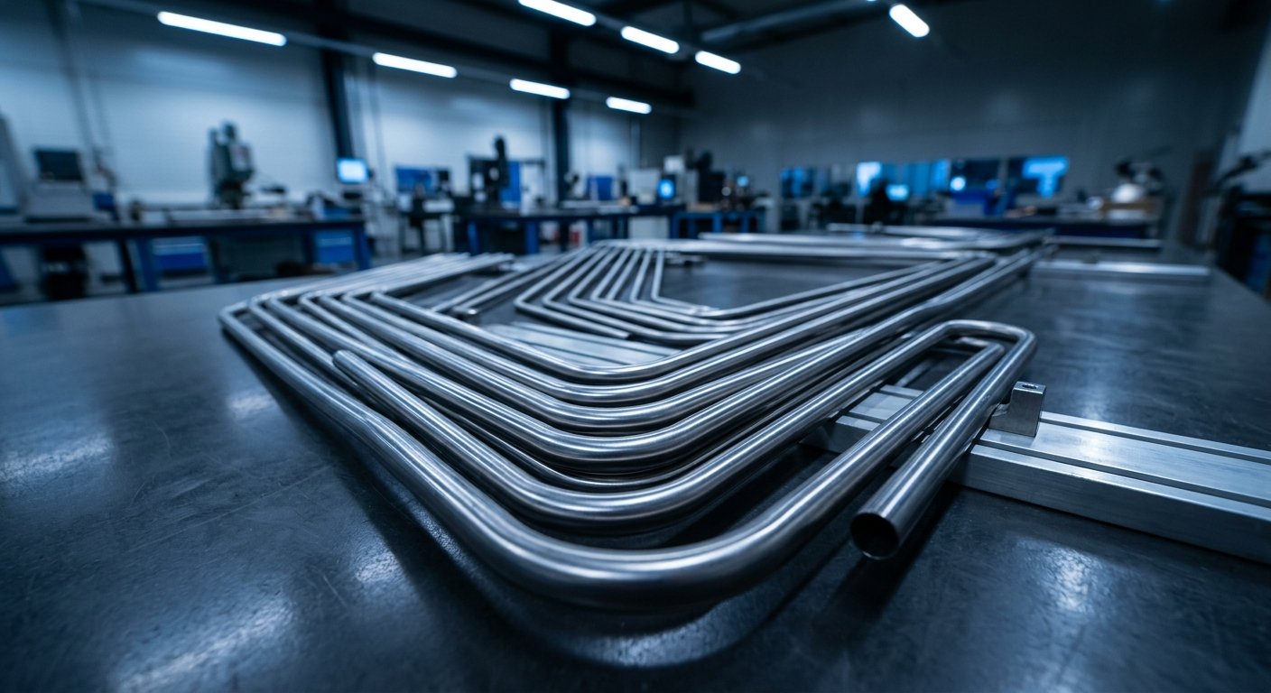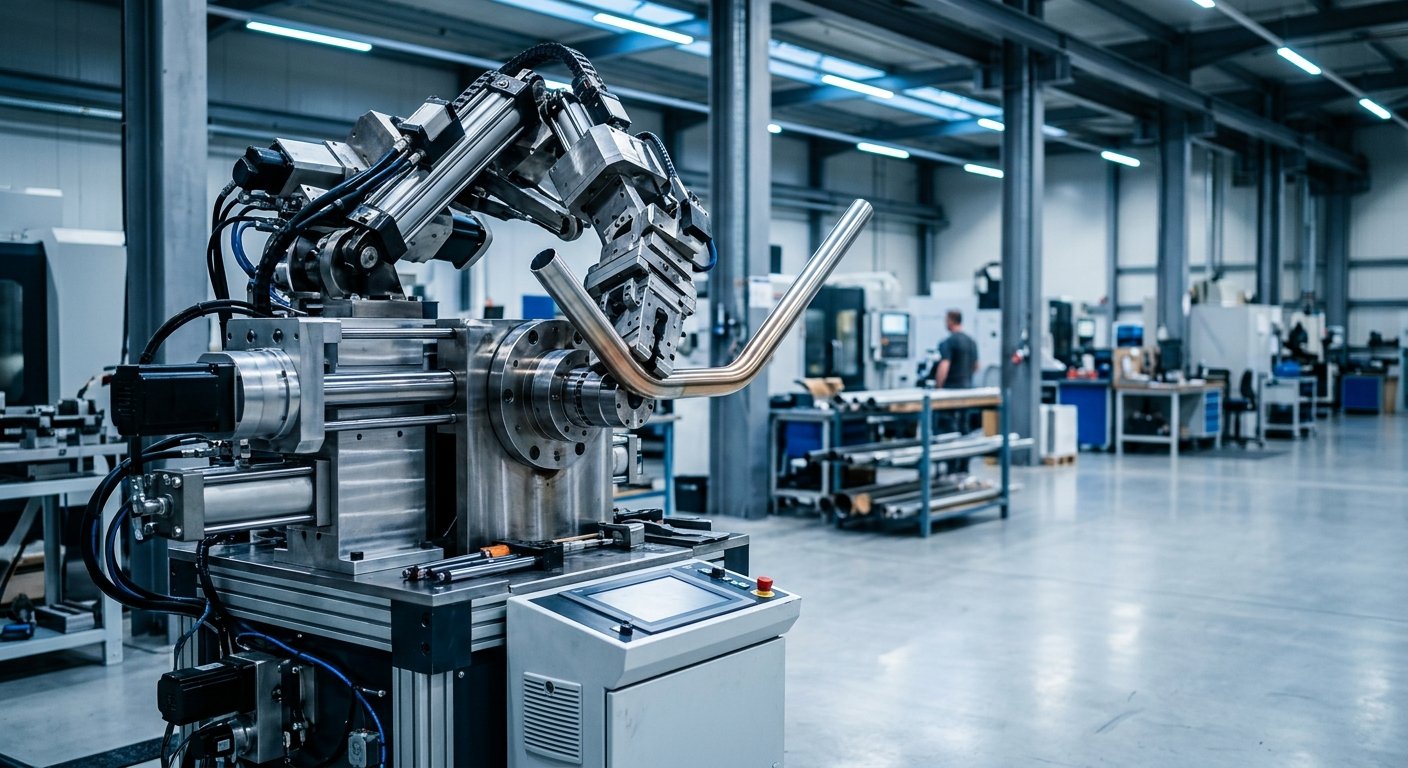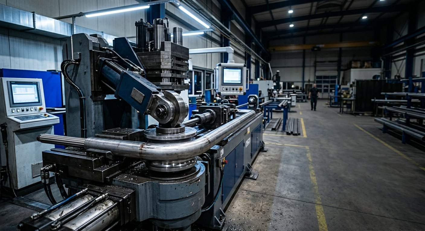
Mandrel bending machines produce tight-radius, wrinkle-free bends in tube and pipe by inserting a flexible internal support—called a mandrel—into the workpiece during the bending cycle. This internal support prevents wall collapse, ovality, and wrinkling that would otherwise occur when bending thin-wall or high-strength tubing. They are the standard solution for aerospace, oil and gas, petrochemical, and defense applications where bend geometry and wall integrity are non-negotiable.
- A mandrel provides internal support during bending, preventing wall collapse and maintaining cross-sectional integrity.
- The mandrel assembly works alongside a wiper die, pressure die, and clamp die to control material flow from multiple directions simultaneously.
- CNC-controlled mandrel tube bending delivers the repeatability and documentation that aerospace, defense, and energy specifications require.
- Mandrel selection—ball count, material, and shank geometry—directly determines achievable bend radius and surface finish.
- Not every application needs a mandrel; understanding when to use one prevents over-engineering and reduces tooling cost.
The Core Mechanics: What Happens Inside the Bend Zone
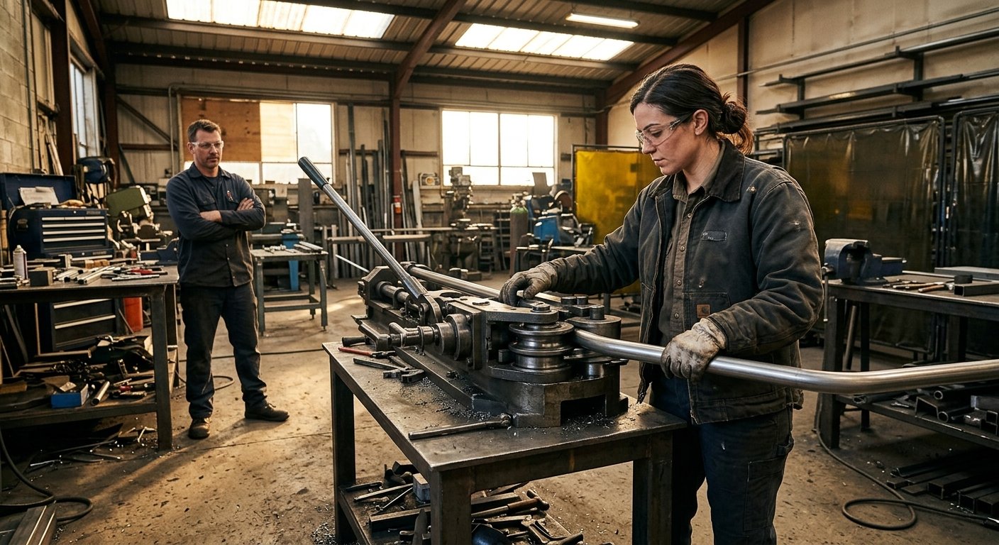
When a tube is bent without internal support, the outer wall stretches and thins while the inner wall compresses and buckles. At tighter centerline radii—typically below 3× the tube outside diameter—these forces overwhelm the material’s ability to self-support, producing ovality, wrinkling, or catastrophic collapse. A mandrel eliminates that problem by occupying the tube’s bore at precisely the point where deformation would otherwise begin.
The mandrel is attached to a rigid shank that extends back through the tube. During the bend cycle, the mandrel tip sits slightly ahead of the bend tangent point—a position called mandrel lead. This forward positioning allows the mandrel to support the tube wall as it wraps around the bend die, then withdraws progressively as the bend completes. Setting mandrel lead correctly is one of the most consequential setup decisions an operator makes; too little lead leaves the outer wall unsupported, while too much can score the tube interior or cause the mandrel to lock up mid-cycle.
Mandrel lead is not a single universal value—it varies by tube OD, wall thickness, material ductility, and bend radius. Experienced setup technicians calculate an initial lead from tooling geometry and then verify it with trial bends, measuring ovality and wall thinning against the applicable specification.
The Five-Component Tooling System
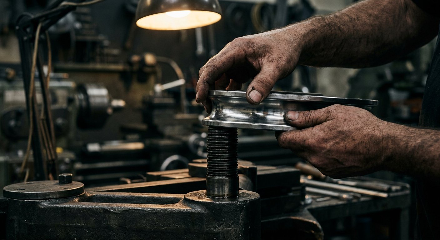
Mandrel bending is not a single tool working alone. Precision tube bending at tight radii requires five coordinated tooling components, each controlling a different aspect of material behavior in the bend zone.
Bend Die
The primary forming tool that establishes the centerline radius. The tube clamps against it and wraps around it as the bend arm rotates. Bend die radius is the single largest factor in determining the finished bend geometry.
Clamp Die
Holds the tube firmly against the bend die at the beginning of the bend. It must grip without slipping yet avoid marking the tube surface—a balance achieved through accurate die-to-tube fit and appropriate clamping pressure.
Pressure Die
Tracks alongside the tube on the outside of the bend, applying controlled force to push material into the bend zone and reduce wall thinning. Pressure die assist—where the die actively feeds forward during the bend—is used for the most demanding thin-wall applications.
Wiper Die
Positioned just behind the bend tangent point on the inner radius side, the wiper die prevents the inner wall from wrinkling by providing a counteracting surface against which the compressing material flows smoothly.
Mandrel
The internal support assembly, which may be a plug, a single-ball, or a multi-ball linked mandrel depending on the required bend radius and tube flexibility. More ball segments allow the mandrel to articulate through tighter radii.
Types of Mandrels and When to Use Each
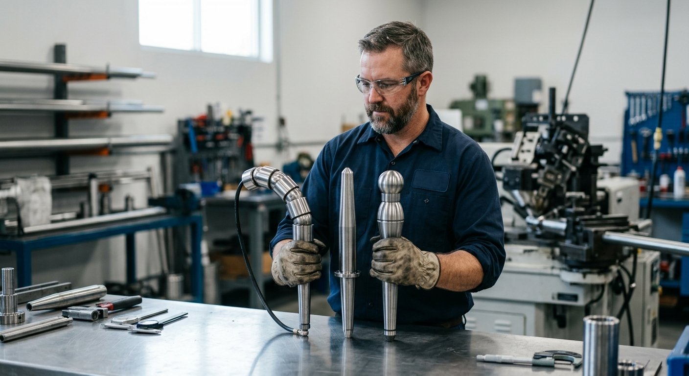
Mandrel selection is driven by the relationship between tube OD, wall thickness, material, and centerline radius. The ASTM standard for drawn seamless aluminum tube and equivalent standards for stainless steel and titanium define wall thickness tolerances that directly influence which mandrel type will achieve a conforming bend.
| Mandrel Type | Best Application | Typical CLR Range |
|---|---|---|
| Plug Mandrel | Thick-wall tube, large radius bends | 3D and above |
| Form / Bullet Mandrel | Medium-wall, moderate radii | 2D–3D |
| Single-Ball Mandrel | Thin-wall, tighter radii | 1.5D–2.5D |
| Multi-Ball Linked Mandrel | Very thin-wall, tight aerospace radii | 1D–2D |
Multi-ball linked mandrels are the most sophisticated option and the most common in precision tube bending for aerospace and defense work. Each ball is connected to the next by a flexible link that allows articulation while still providing a continuous supporting surface against the tube’s inner diameter. The number of balls required increases as centerline radius decreases relative to tube OD.
Mandrel material matters as much as mandrel geometry. Chrome-plated steel mandrels suit most steel and stainless applications, while aluminum bronze mandrels are preferred for thin-wall titanium or work-hardening alloys where galling is a risk. Always confirm mandrel material compatibility with your tube alloy before committing to a tooling order.
CNC Control: Turning Process Physics Into Repeatability
Manual and semi-automatic mandrel benders can produce quality bends, but modern production demands—especially in aerospace and defense—require documented repeatability across hundreds or thousands of identical parts. That is where CNC tube benders become essential. A CNC system controls bend angle, rotation between bends, linear feed distance, mandrel position, pressure die force, and wiper die position through a programmable logic interface. Every parameter is stored in a part program, eliminating operator-to-operator variation and creating a traceable production record.
Multi-stack CNC mandrel benders can execute compound bend sequences—multiple bends in different planes along a single tube—automatically, without removing the part between operations. This capability is critical for hydraulic and fuel line assemblies in aircraft, where a single tube may pass through multiple structural bays and require five or more bends in three-dimensional space. The FAA Advisory Circular on aircraft fuel systems outlines dimensional and integrity requirements that make documented, repeatable CNC bending a practical necessity rather than a preference.
A CNC part program doesn’t just store angles—it stores the entire physics of the bend, making the thousandth part as accurate as the first.
Material Behavior and Springback Compensation
Every metal springback after bending—the elastic portion of the deformation recovers when tooling pressure is released. For mild steel, springback may be minimal and easily compensated by overbending a fixed amount. For aerospace-grade titanium alloys or precipitation-hardened stainless steels, springback can be substantial and variable between heats of the same alloy. CNC mandrel bending systems address this through programmable springback compensation: the machine overbends by a calculated angle, and the part springs back to the target geometry.
Determining the correct compensation factor requires test bends and measurement, ideally with CMM (coordinate measuring machine) verification tied back to the part’s 3D model. This is standard practice when bending to aerospace specifications and is one reason NASA engineering standards for tubing and fluid systems require process qualification documentation before production begins.
When Mandrel Bending Is—and Isn’t—the Right Choice
Mandrel bending adds tooling complexity and setup time compared to rotary draw bending without a mandrel. For thick-wall, large-radius bends in ductile materials, a mandrel may not be necessary and adds cost without benefit. The decision matrix is straightforward:
- Use mandrel bending when CLR is below 3× OD, wall thickness is thin relative to OD, surface finish inside the bend must be smooth, or the specification explicitly requires it.
- Evaluate alternatives when bending heavy-wall pipe at large radii, when material is highly ductile and tolerances are loose, or when production volume is too low to justify mandrel tooling amortization.
For high-stakes applications in oil and gas pipelines, petrochemical process piping, or defense hydraulic systems, the cost of mandrel tooling is easily justified by the cost of a rejected assembly or a failed pressure test. Our custom bending solutions engineering team routinely evaluates these trade-offs for customers specifying equipment for demanding service conditions.
Frequently Asked Questions
What is the difference between mandrel bending and rotary draw bending?
Rotary draw bending describes the machine motion—the tube is clamped to a rotating bend die and drawn around it. Mandrel bending describes the tooling configuration—an internal mandrel supports the tube bore during the bend. Most precision mandrel tube bending uses both techniques simultaneously: a rotary draw machine equipped with a mandrel assembly. The two terms are often used together but describe different aspects of the process.
How do I know how many mandrel balls I need?
Ball count is determined by the D/t ratio (outside diameter divided by wall thickness) and the centerline radius relative to OD. As a general rule, the thinner the wall and the tighter the radius, the more balls are needed to maintain continuous inner-diameter support through the bend arc. Tooling engineers calculate the required ball count from these parameters, and experienced mandrel bending equipment manufacturers can confirm the right configuration for your specific tube and bend requirements.
Can mandrel bending be used on titanium and high-strength alloys?
Yes, but it requires careful tooling material selection, lubrication, and springback compensation. Titanium’s combination of high strength-to-weight ratio, significant springback, and susceptibility to galling makes it one of the more demanding mandrel bending materials. Aluminum bronze mandrels, appropriate bending lubricants, and CNC-controlled springback compensation are standard practices for titanium tube bending in aerospace applications.
What specifications govern tube bend quality in aerospace applications?
Aerospace tube bending is typically governed by customer drawing requirements combined with industry standards such as AS9100 quality management requirements and applicable ASTM material specifications. Specific aircraft programs may invoke additional requirements for wall thinning limits, ovality tolerances, and surface finish. Process qualification documentation is commonly required before production bending begins on flight-critical tube assemblies.
How does CNC control improve mandrel bending outcomes?
CNC control stores every process parameter—bend angle, feed length, rotation, mandrel position, pressure die force—in a repeatable part program. This eliminates operator-to-operator variability, enables automatic springback compensation, and creates a documented production record. For multi-bend tube assemblies with tight positional tolerances, CNC mandrel bending machines are the only practical way to achieve consistent results across production runs.
Selecting the Right Mandrel Bending Equipment
Equipment selection starts with the application envelope: tube OD range, wall thickness range, tightest required CLR, materials to be bent, production volume, and any applicable industry specifications. From that data, the right machine capacity, mandrel system, and control architecture can be defined. Hines Bending Systems has engineered precision tube and pipe bending equipment for 50 years, supplying NASA, military, and demanding industrial customers with American-manufactured machines built to handle the full range of these requirements.
Whether you’re specifying equipment for high-volume aerospace fuel line production or a custom one-off application in a petrochemical facility, the path to the right machine starts with an honest engineering conversation. Explore our tube bending machines and pipe bending machines to understand the platform options, then connect with our team to discuss your specific requirements.
Discuss Your Mandrel Bending Application
Our engineering team will review your tube specifications, bend requirements, and production goals to recommend the right mandrel bending solution for your application.

About Hines Bending Systems
Hines Bending Systems is a leading American manufacturer of precision tube and pipe bending equipment serving aerospace, energy, oil & gas, petrochemical, and defense industries. With 50 years of proven expertise and a track record of supplying NASA and military clients, Hines delivers custom bending solutions for demanding applications ranging from high-volume production to specialized one-off projects. The company combines deep technical knowledge with comprehensive support including training and service, positioning itself as a partner in customer success rather than just an equipment supplier. Visit hinesbending.com →