Aerospace manufacturing tolerances leave almost no room for error. A hydraulic line routed through a fighter jet airframe or a fuel tube assembly in a commercial aircraft engine must meet exact bend angles, radii, and wall thickness requirements—every single time. Selecting the wrong tube bending machine for aerospace work doesn’t just result in scrap; it can create compliance failures, production delays, and costly engineering rework.
This guide breaks down the critical machine specifications engineers and procurement specialists need to evaluate when sourcing aerospace tube bending equipment in 2026, covering CNC controls, tooling configurations, material compatibility, and the technical benchmarks that separate production-grade machines from truly aerospace-capable systems.
Why Aerospace Bending Demands Specialized Equipment
Commercial and defense aerospace programs work with a demanding range of tubing materials—titanium alloys, Inconel, stainless steel, aluminum alloys like 6061 and 7075, and CRES (corrosion-resistant steel). Each material behaves differently under bending force, particularly regarding springback, wall thinning, and ovalization. Standard industrial tube benders often lack the precision controls, tooling support, and repeatability required to consistently meet aerospace specifications such as those outlined under ASTM nonferrous tubing standards or AS9100 quality management requirements.
Aerospace tube bending also requires documented process control. Many programs—whether FAA-regulated commercial builds or military contracts—mandate traceability from raw material through finished bend. That means your bending equipment must support data logging, operator authentication, and real-time parameter monitoring.
Key Machine Specifications to Evaluate
Bending Capacity and Tube Diameter Range
Aerospace applications span a wide diameter range. Hydraulic and pneumatic lines commonly run from 0.25 inches up to 2 inches OD, while structural and fuel system tubing can reach 4 inches or larger in some airframe applications. A capable aerospace tube bending machine should clearly state:
- Minimum and maximum tube OD capacity
- Wall thickness range (typically expressed as a D/t ratio)
- Maximum bend angle (most aerospace machines achieve 190° or greater)
- Minimum centerline radius (CLR) relative to tube OD
A tight CLR—sometimes called a tight-radius or 1D bend—places the greatest stress on tube material and demands the most from your mandrel system and pressure die configuration. Many aerospace specifications call for 1.5D to 2D bends, but structural assemblies occasionally require 1D bends, which pushes machines to their engineering limits.
CNC Control Systems and Programming Capabilities
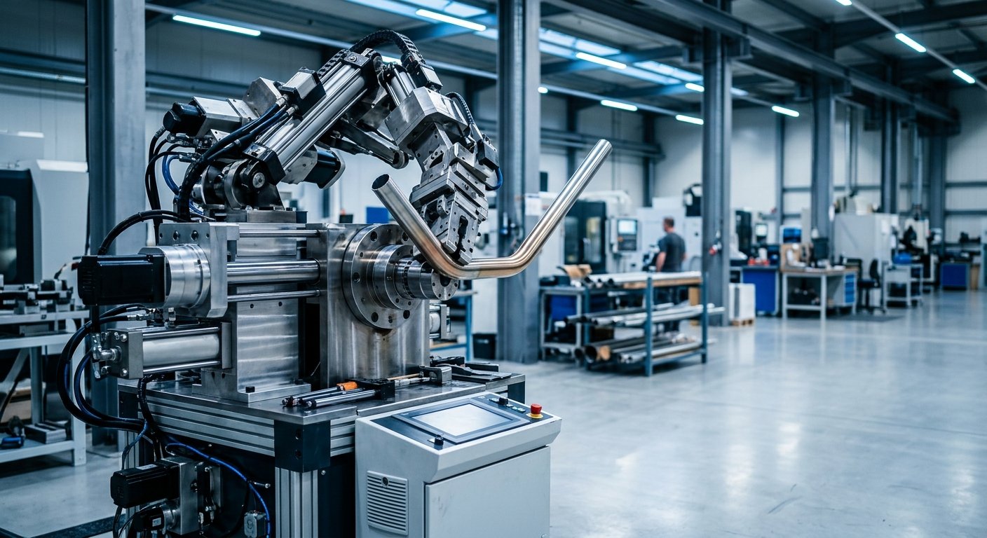
Modern CNC tube benders have become the standard for aerospace production environments, and for good reason. CNC controls provide the programmable precision that manual and semi-automatic machines cannot match at scale. When evaluating CNC control specifications, engineers should look for:
- Multi-stack tooling capability: Allows a single machine setup to produce multiple bend radii without retooling between runs
- YBC axis control: Simultaneous management of bend angle (Y), boost (B), and carriage (C) axes for tight-radius bends without wrinkling
- Springback compensation: Automatic angle correction based on material-specific springback data entered into the program
- Part program storage: Enough memory to store hundreds of aerospace part programs with revision control
- Data output and logging: Real-time parameter capture for process traceability, essential for AS9100 compliance
Industry data consistently shows that CNC-controlled bending reduces setup time and operator error significantly on complex aerospace tube assemblies compared to manual methods. For aerospace programs running mixed-part schedules, this capability isn’t optional—it’s fundamental.
Mandrel and Tooling Specifications
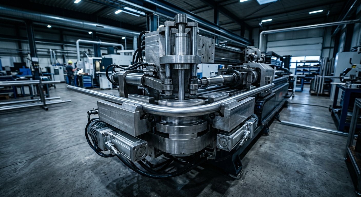
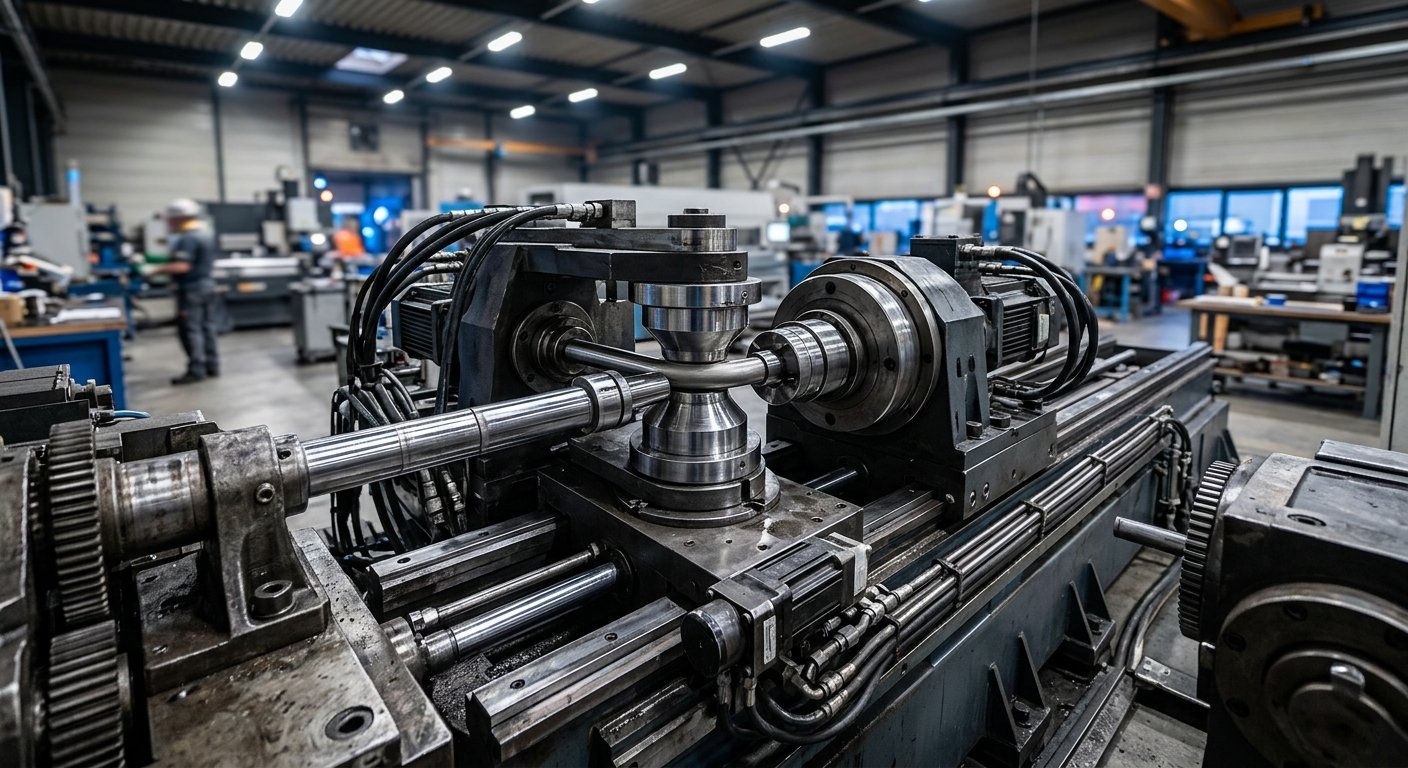
Mandrel bending machines are the workhorse of precision aerospace tube bending. A mandrel—inserted inside the tube during the bend—prevents collapse and ovalization, which are unacceptable in pressurized aerospace fluid systems. The mandrel specification you need depends on your application:
- Ball mandrels with multiple linked balls are suited to tight-radius bends and thin-wall tubing
- Plug mandrels work for thicker-wall tubing at larger radii
- Wiper dies paired with mandrels prevent wrinkling on the inner radius
Tooling material matters too. Aerospace tooling is commonly manufactured from hardened tool steel or aluminum bronze, with surface finishes optimized for specific tube materials. Titanium, for example, is prone to galling and requires tooling with appropriate surface treatment or material pairing.
Hines Bending Systems engineers custom tooling packages for specific aerospace applications, drawing on 50 years of tube and pipe bending expertise to match mandrel geometry, wiper die configuration, and pressure die force to the exact material and geometry being produced.
Critical Performance Benchmarks for Aerospace Applications
Repeatability and Angular Accuracy
Aerospace assemblies are built to engineering drawings with tolerances that are often tighter than general industrial work. Bend angle repeatability of ±0.1° or better is typically required for hydraulic and fuel system tubing. Wall thinning should remain within 15–20% of nominal wall thickness for most aerospace specifications, though some programs allow less.
Ovality—the distortion of the tube’s circular cross-section through the bend—is another critical benchmark. The NASA technical standards program and related engineering documentation outline acceptable ovality limits for pressurized systems, typically requiring that cross-sectional distortion remain below 5% in critical fluid-carrying lines.
Pressure Die and Boost System Performance
The pressure die supports the straight portion of the tube during bending and, when equipped with a boost function, pushes material into the bend zone to counteract wall thinning. Aerospace-grade machines should specify:
- Pressure die force capacity in pounds or kilonewtons
- Boost ratio capability as a percentage of bend arm speed
- Closed-loop hydraulic control for consistent force application
Machines without closed-loop control tend to show more variability across production runs, particularly when processing work-hardening materials like Inconel or titanium that are common in defense and commercial aerospace programs.
Aerospace-Specific Machine Configurations
Not every aerospace tube bending application has the same production profile. High-volume commercial aircraft component programs have different requirements than a specialized defense prototype build. The right machine configuration depends on your production model:
- Single-stack CNC rotary draw benders are well-suited to dedicated production lines running a single tube diameter and radius combination at volume
- Multi-stack CNC tube benders offer the flexibility to run multiple radii in a single setup, ideal for mixed-part aerospace shops or programs with frequent design revisions
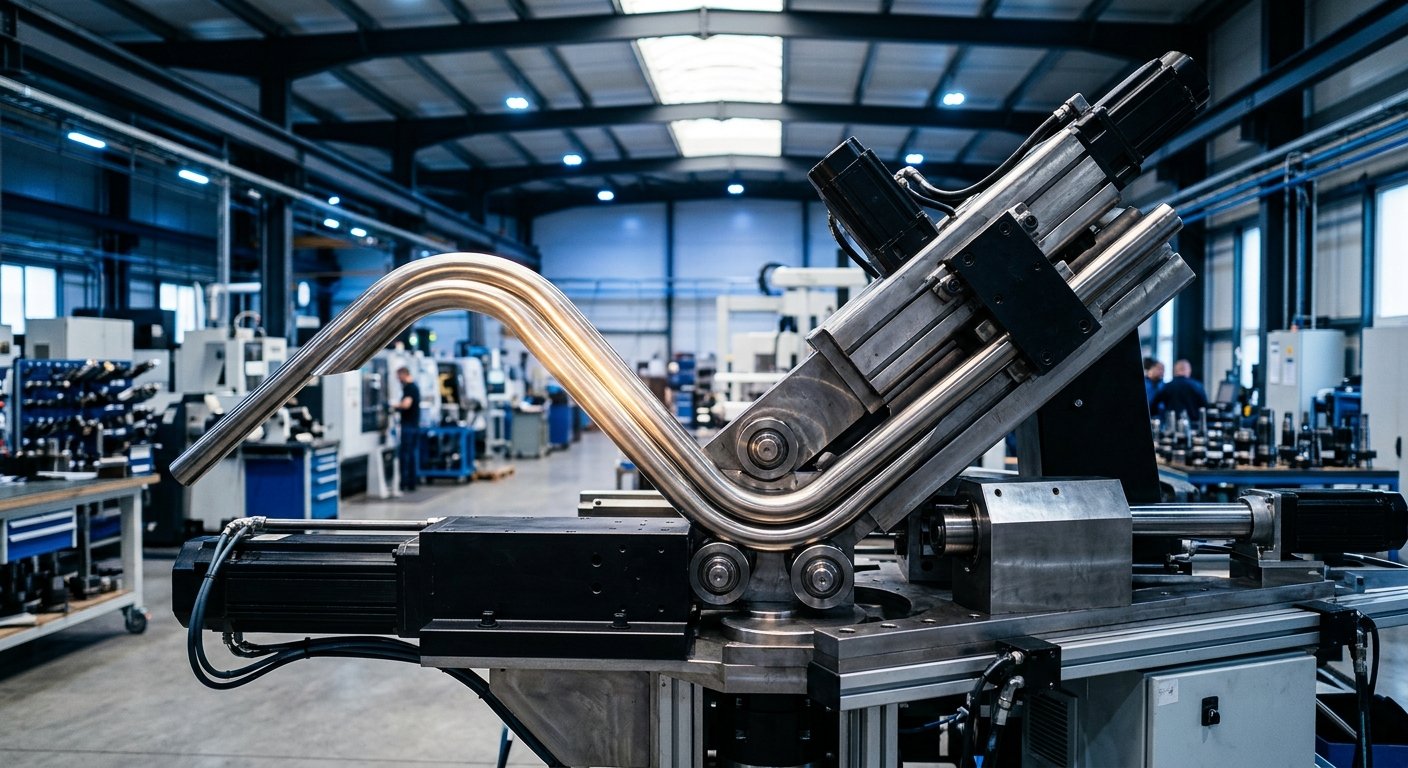
- Right-left CNC benders bend in both directions without re-chucking, critical for complex 3D aerospace tube assemblies
- Servo-electric bending machines provide high positional accuracy and energy efficiency with lower hydraulic fluid maintenance requirements—an increasingly common preference in aerospace facilities with strict contamination control requirements
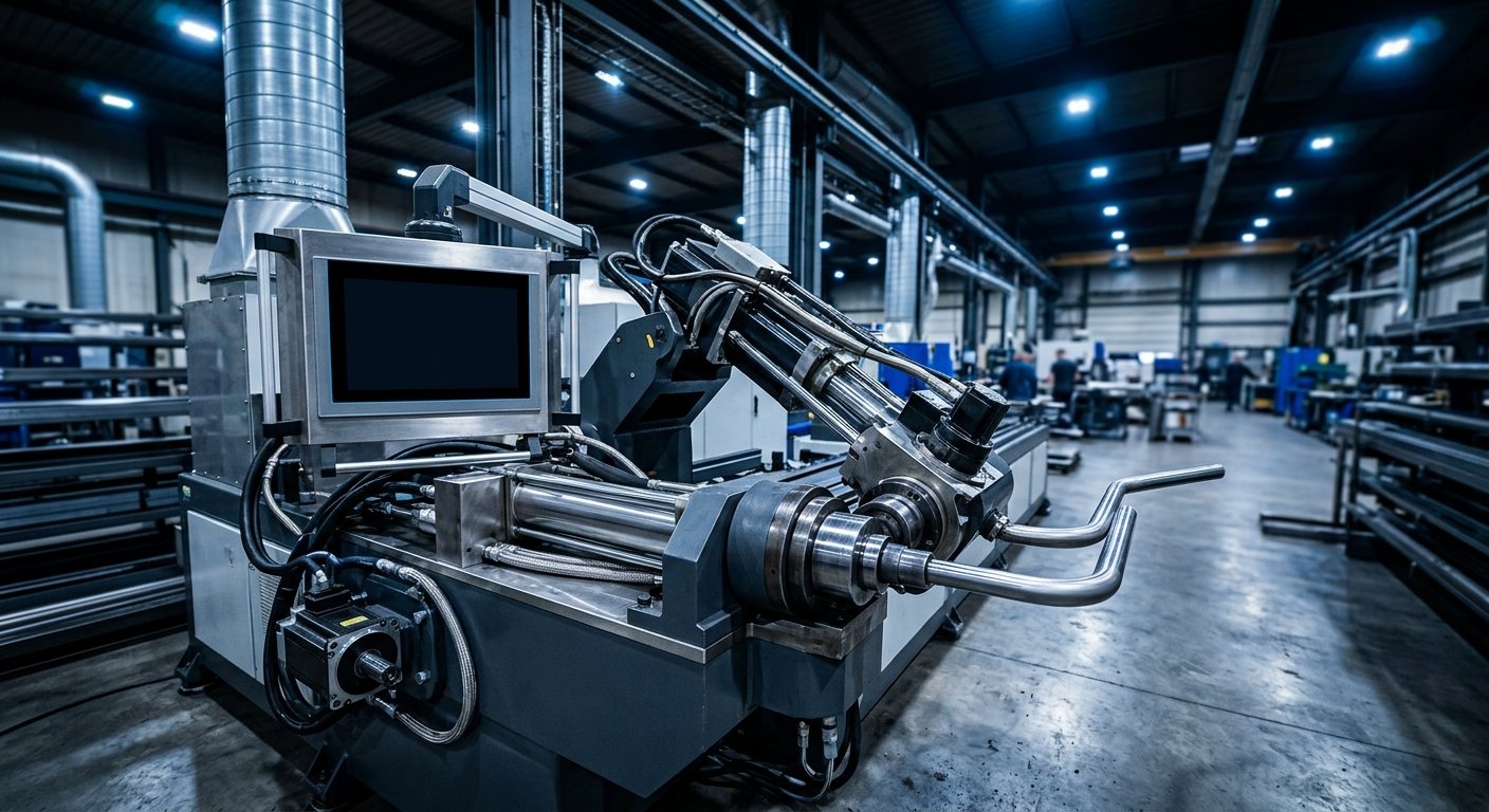
Hines offers a range of tube bending machines configured specifically for precision aerospace and defense work, with American-manufactured builds trusted by NASA and military clients across demanding programs.
Material Considerations in 2026
Aerospace material portfolios continue to evolve. Additive manufacturing and composite structures are displacing some traditional tubing in structural roles, but fluid systems, hydraulics, fuel, and environmental control systems still rely heavily on precision-bent metallic tubing. In 2026, aerospace bending operations are increasingly processing:
- Titanium Grade 5 (Ti-6Al-4V): Offers high strength-to-weight ratio but requires careful springback management and heated tooling in some applications
- Inconel 625 and 718: Used in high-temperature engine applications; demands high bending force capacity and premium tooling
- Stainless 21-6-9: Popular in aerospace hydraulic systems for its cryogenic properties
- Aluminum 7075-T6: Lightweight structural applications where formability is limited
The FAA’s transport aircraft certification framework governs material and process qualification requirements for tubing used in certified aircraft, adding another layer of documentation and process control that your bending equipment must support.
Frequently Asked Questions
What is the minimum bend radius for aerospace tube bending?
Minimum centerline radius (CLR) in aerospace applications typically ranges from 1D to 3D, where D equals the tube outside diameter. Tighter radii require mandrel bending machines with ball mandrels and wiper dies. The actual minimum achievable depends on tube material, wall thickness, and machine tooling configuration.
What CNC tube bender features are most important for aerospace work?
The most critical features include multi-axis control (YBC at minimum), springback compensation, closed-loop force control on the pressure die, part program storage with revision control, and real-time data logging for process traceability. AS9100-compliant facilities also require operator authentication and documented parameter records.
Can one machine handle both titanium and aluminum aerospace tubing?
A properly specified CNC mandrel bending machine can process both materials with tooling changeovers between runs. However, titanium requires higher bending forces, specialized tooling materials to prevent galling, and precise springback compensation. Machine capacity must be sized for the most demanding material in your production mix.
How does wall thinning affect aerospace tube bending specifications?
Wall thinning occurs on the outer radius of a bend and reduces the tube’s pressure-carrying capacity. Most aerospace fluid system specifications limit thinning to 20% of nominal wall thickness or less. Mandrel bending with boost assist on the pressure die is the primary method for controlling thinning within specification.
What documentation should an aerospace tube bending machine support?
At minimum, aerospace-capable machines should output bend parameter logs (angle, force, speed), support part program version control, and allow export of production records for quality documentation. Many defense programs also require integration with shop floor data systems and first-article inspection reporting.
Partnering for Aerospace Precision
Selecting aerospace tube bending equipment is a long-term production decision. The machine specification you choose today will shape your shop’s capability, throughput, and quality compliance for years. Getting that specification right requires more than reading a datasheet—it requires understanding how a machine’s engineering interacts with your specific materials, geometries, and quality requirements.
Hines Bending Systems has supported aerospace and defense manufacturers with American-built precision bending equipment for 50 years, providing not just equipment but the application expertise, custom tooling, and ongoing service support that demanding programs require. Explore our full range of aerospace tube bending solutions or contact our engineering team to discuss your specific application requirements.