In oil and gas applications, pipe bending must meet strict code requirements under ASME B31.3, B31.4, and B31.8—where internal pressures can exceed 10,000 psi and ovality must stay within 8% of nominal diameter (or 3–5% in critical service). Wall thickness retention, bending method selection, material compatibility, and CNC repeatability are the five specifications that determine whether a bending system can be qualified for production work.
- Post-bend wall thickness must remain at or above the pressure design minimum per ASME B31.3; engineers typically build in a 12–15% thinning allowance for tight-radius bends.
- Ovality limits are 8% for standard pressure service and 3–5% for critical or high-pressure applications.
- Induction bending suits large-diameter, wide-radius applications (3D–40D); rotary draw mandrel bending suits tighter radii and smaller-diameter production runs.
- Duplex stainless steels have approximately twice the yield strength of 316L, requiring higher bending forces and springback compensation.
- CNC control with closed-loop angle feedback and data logging is essential for code compliance and fitness-for-service documentation.
Whether you’re sourcing industrial pipe benders for a new pipeline project, evaluating mandrel bending machines for a refinery expansion, or specifying induction bending for large-diameter pressure piping, understanding which technical parameters actually drive performance—and which are secondary—separates successful projects from costly failures. This guide focuses on the specifications that carry the most weight in demanding oil and gas applications, and how to evaluate oil and gas pipe bending equipment against those requirements.
Why Oil & Gas Demands More from Pipe Bending Equipment
The oil and gas sector operates under some of the most demanding service conditions in industry. Piping systems routinely face:
- Internal pressures exceeding 10,000 psi in wellhead and manifold applications
- Temperature swings from cryogenic LNG service to high-temperature refinery operations
- Corrosive media including hydrogen sulfide (H₂S), CO₂, chlorides, and sour crude
- Dynamic loading from vibration, surge, and seismic forces in offshore structures
- Regulatory compliance under ASME B31.3, ASME B31.4, and B31.8 piping codes
These conditions mean that bending processes must preserve material integrity, dimensional accuracy, and mechanical properties with precision that generic bending equipment simply cannot deliver. According to the American Society of Mechanical Engineers, bends in pressure piping must meet strict requirements for wall thickness, ovality, and surface condition to remain code-compliant—requirements that demand purpose-built, precision equipment.
Critical Specification #1: Wall Thickness Retention
Heavy wall pipe bending is among the most technically demanding processes in industrial fabrication. When pipe is bent, the outer radius experiences tensile stress and wall thinning, while the inner radius undergoes compression and potential wrinkling or buckling. The extent of wall thinning is directly related to the bend radius, material properties, and bending method.
For oil and gas applications, the key metric is the minimum wall thickness at the extrados (outer bend radius) after forming. ASME B31.3 specifies that the calculated wall thickness at any point in a bend must remain at or above the pressure design thickness—meaning you must account for thinning before you start bending.
The specifications to evaluate in your bending equipment include:
- Mandrel design and positioning accuracy: Internal mandrel support is critical for heavy-wall bends. Ball-type mandrels with proper wiper die support prevent collapse and ovality.
- Clamp and pressure die force control: CNC-controlled force application prevents excessive thinning or wrinkling during the bending cycle.
- CLR/D ratio capability: The centerline radius-to-diameter (CLR/D) ratio determines how tight a bend the machine can execute. Most oil and gas specifications require CLR/D ratios of 1.5D to 5D depending on service class.
Ovality and wall thinning interact: a machine that meets your ovality target on thin-wall carbon steel may perform very differently on heavy-wall duplex or nickel alloy. Always request production-trial data—not theoretical calculations alone—for the specific pipe sizes and materials you intend to run.
Critical Specification #2: Ovality and Dimensional Tolerance
Ovality—the difference between the maximum and minimum outer diameter at the bend—is a spec that directly affects flow characteristics, fitting compatibility, and pressure capacity. For high-pressure piping, most engineering standards limit ovality to 8% or less of nominal diameter, with more stringent requirements (3–5%) common in critical applications.
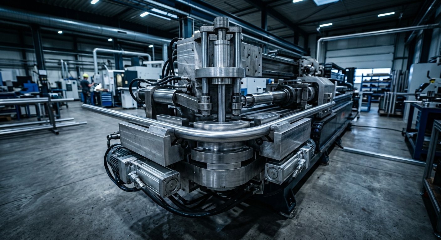
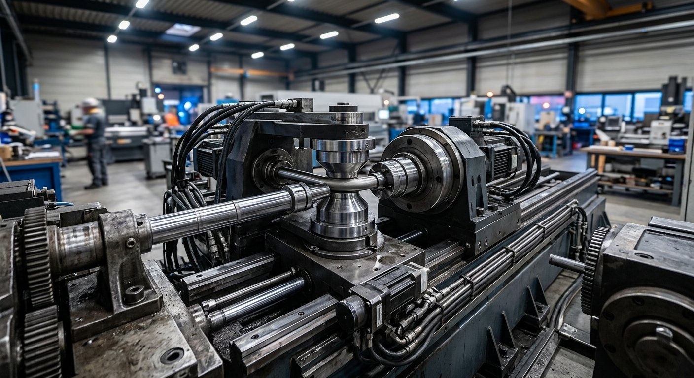
CNC mandrel bending machines achieve the tightest ovality control through synchronized die force management and precisely engineered tooling. When evaluating pipe bending equipment for oil and gas use, request documentation of achievable ovality across the pipe sizes and wall thicknesses you intend to run. This data should come from actual production trials, not theoretical calculations alone.
The degree of bend control achievable with modern CNC rotary draw machines—down to fractions of a degree—makes them indispensable for complex assemblies where fit-up tolerance is tight.
Critical Specification #3: Bending Method Selection
Two methods dominate oil and gas pipe bending: rotary draw mandrel bending and induction bending. Each has a distinct performance envelope, and selecting the wrong method for a given application can compromise quality or economics.
| Criterion | Rotary Draw Mandrel Bending | Induction Bending |
|---|---|---|
| Pipe diameter range | Smaller-diameter pipe | Large-diameter pipe |
| Bend radius (CLR/D) | Tight radii, 1.5D–5D typical | Wide radii, 3D–40D |
| Typical applications | Instrument headers, small-bore process piping, hydraulic control lines, offshore umbilical tubes | Transmission pipelines, offshore risers, structural applications |
| Production suitability | High-volume standardized runs | Large, one-off or low-volume bends |
| Key process variables | Mandrel design, die force, CNC angle control | Heating frequency, temperature uniformity, push speed |
| Post-bend heat treatment | Material-dependent | Often required (e.g., P91 chrome-moly) |
Rotary Draw Mandrel Bending
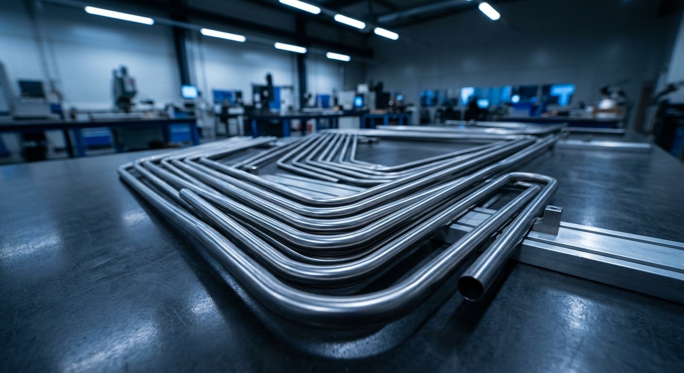
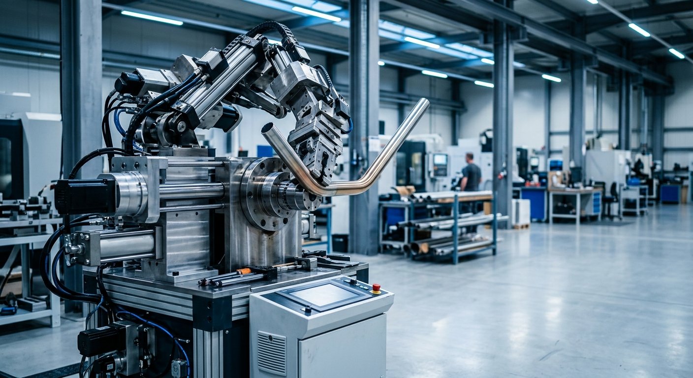
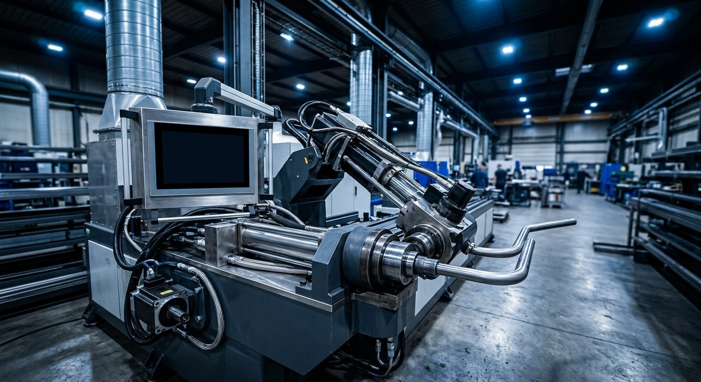
Rotary draw bending, executed on mandrel bending machines, is the method of choice for smaller-diameter, tighter-radius bends in stainless steel, chrome-moly alloys, duplex stainless, and carbon steel. It provides excellent dimensional repeatability and is well-suited for high-volume production runs of standardized bends. In oil and gas, it is commonly used for instrument tubing headers, small-bore process piping, hydraulic control lines, and offshore umbilical tube fabrication.
Induction Bending
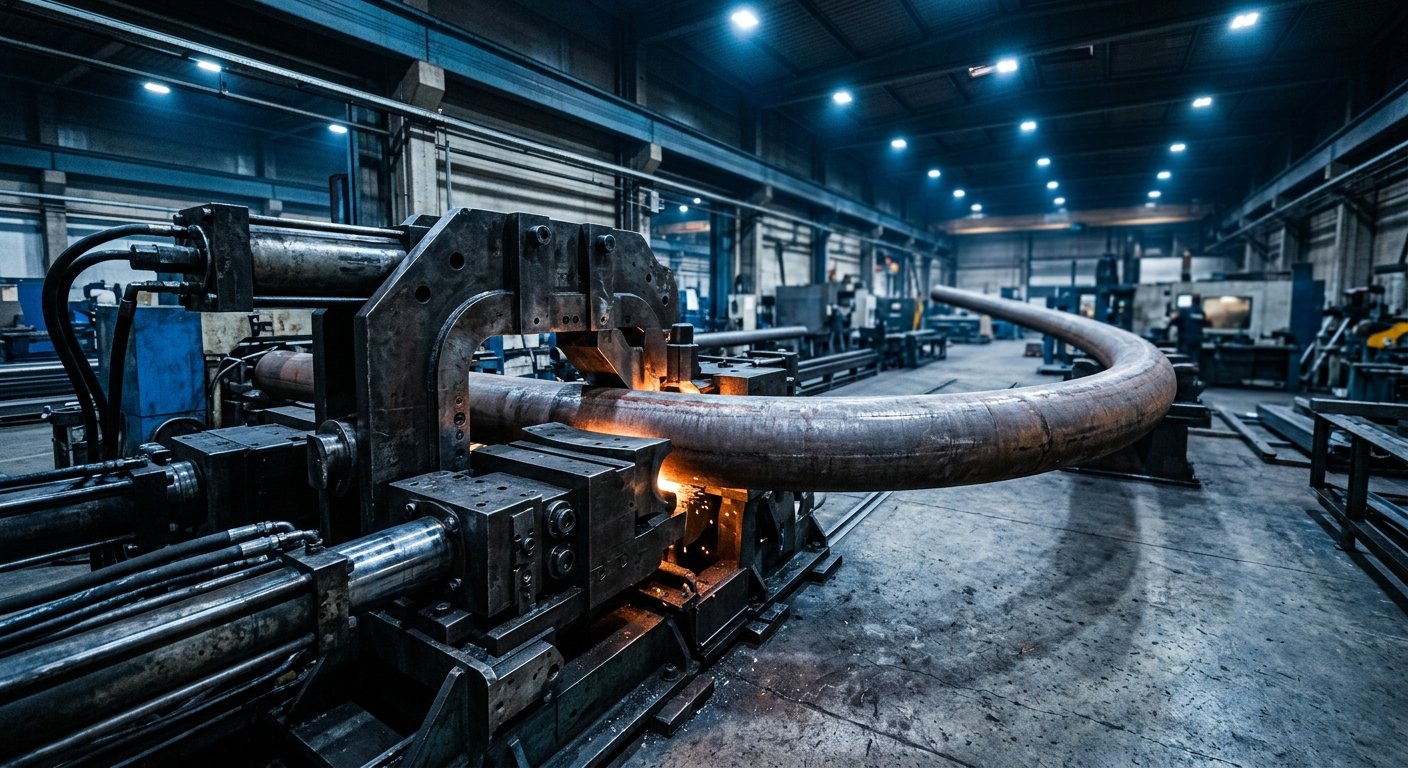
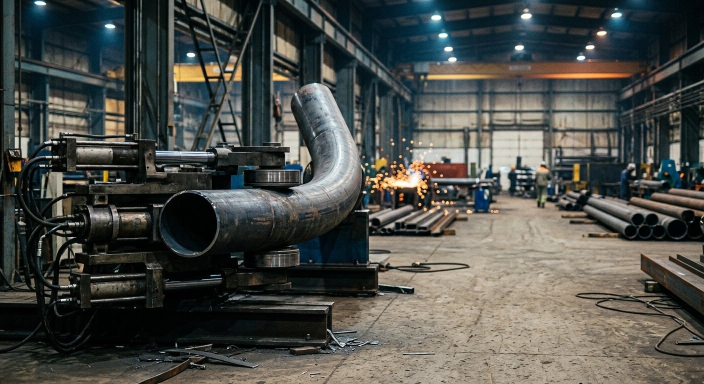
Induction bending uses a localized, high-frequency induction heating coil to heat a narrow band of pipe just ahead of the bending arc, allowing large-diameter, heavy-wall pipe to be formed with relatively low force. This method is standard for large-diameter transmission pipelines, offshore risers, and structural applications where CLR/D ratios of 3D to 40D are required. The key induction bending specifications to evaluate include heating frequency (which determines the depth of heat penetration), temperature uniformity across the pipe cross-section, and push speed control. Post-bend heat treatment requirements—particularly for P91 chrome-moly and other creep-resistant alloys—must also be factored into the process specification.
Critical Specification #4: Material Compatibility and Tooling
Oil and gas piping encompasses an unusually wide material range: carbon steel (API 5L grades), austenitic stainless steels (316L, 317L), duplex and super-duplex stainless (2205, 2507), nickel alloys (Inconel 625, 825), and chrome-moly steels (P11, P22, P91). Each material has distinct springback characteristics, work-hardening behavior, and sensitivity to improper tooling contact.
The precision tube bending equipment and tooling must be matched to material properties, not treated as interchangeable. For example:
- Duplex stainless steels have approximately twice the yield strength of 316L, requiring higher bending forces and careful springback compensation
- Nickel alloys work-harden rapidly and require slower bend speeds and appropriate tooling surface finishes to prevent galling
- Carbon steel seam-welded pipe requires attention to weld seam orientation to avoid preferential buckling at the weld line
The American Petroleum Institute publishes specifications covering pipe grades and dimensional standards that inform tooling design—proper tooling begins with a thorough review of the pipe’s dimensional tolerances as manufactured.
Super-duplex stainless steels, P91 chrome-moly, and nickel alloys present the greatest material challenges. They require carefully matched tooling, controlled bending parameters, and often post-bend heat treatment to restore mechanical properties. Do not assume tooling qualified on 316L stainless will perform acceptably on these grades.
Critical Specification #5: CNC Control and Repeatability
In production environments—particularly offshore module fabrication or refinery piping spoolshops—the ability to reproduce identical bends across a production run without operator-to-operator variation is a core requirement. Modern CNC bending control systems store complete bend programs including bend angle, CLR, rotation, and die force parameters, enabling consistent reproduction across shifts and operators.
When evaluating CNC capabilities, look for systems that provide:
- Closed-loop angle feedback with springback compensation
- Real-time monitoring of process variables (force, position, speed)
- Data logging for traceability and quality records
- Integration with CAD/CAM piping design software
Traceability is increasingly important as oil and gas operators require complete material and process records for regulatory compliance and fitness-for-service documentation.
Matching Equipment to Application: A Practical Framework
Selecting the right industrial pipe benders for a specific oil and gas application requires matching machine capability to the most demanding combinations of pipe OD, wall thickness, material grade, bend radius, and production volume you expect to encounter. Over-specifying wastes capital; under-specifying creates quality problems and potential safety exposure.
Define the pipe size range
Establish the OD and wall thickness extremes you will encounter across the project. These set the outer bounds on machine capacity and tooling requirements.
Identify the tightest CLR/D ratio required
The minimum centerline radius-to-diameter ratio drives mandrel design, die geometry, and whether rotary draw or induction bending is appropriate.
List all materials and their yield strength range
Material properties determine required bending forces, springback compensation, tooling surface finish, and whether post-bend heat treatment is needed.
Determine production volume
High-volume runs of standardized bends favour CNC rotary draw machines with fast tooling changeover; one-off large-diameter spools may point to induction bending.
Specify applicable piping codes and documentation requirements
ASME B31.3, B31.4, and B31.8 each carry specific bend quality requirements. Documentation and traceability requirements must be built into the CNC system specification.
Evaluate tooling changeout time
If multiple pipe sizes will run on one machine, changeout time directly affects throughput. Request actual changeout times, not theoretical minimums, from equipment suppliers.
This framework ensures you’re comparing equipment on the specifications that actually determine whether it can do your job—not just headline capabilities that may not apply to your application.
Frequently Asked Questions
What is the difference between induction bending and mandrel bending for oil and gas pipe?
Induction bending uses localized heat to form large-diameter, heavy-wall pipe at wide radii and is standard for transmission pipelines and risers. Mandrel bending uses internal tooling support for tighter-radius bends on smaller-diameter pipe and is preferred for process piping, instrument headers, and high-volume production of standardized bends.
What wall thinning is acceptable in oil and gas pipe bends?
Acceptable wall thinning depends on the applicable piping code and service conditions. ASME B31.3 requires that post-bend wall thickness remain at or above the pressure design minimum. Engineers typically specify starting wall thickness with a thinning allowance built in, often 12–15% for tight-radius bends, though this must be verified by calculation for the specific material and CLR/D ratio.
What ovality limits apply to bent pipe in pressure service?
Most pressure piping codes and project specifications limit ovality to 8% of nominal outside diameter for standard service, with 3–5% limits common in critical or high-pressure applications. Equipment selection and tooling quality directly determine achievable ovality.
What materials are most challenging for oil and gas pipe bending?
Super-duplex stainless steels, P91 chrome-moly, and nickel alloys present the greatest challenges due to high yield strength, work-hardening behavior, and sensitivity to heat input. These materials require carefully matched tooling, controlled bending parameters, and often post-bend heat treatment to restore mechanical properties.
How important is CNC control for oil and gas pipe bending?
CNC control is essential for production environments requiring repeatability, traceability, and documentation. Modern CNC bending systems store complete programs, log process data, and enable springback compensation—all critical for meeting piping code requirements and quality documentation standards.
Partner with Proven Expertise for Demanding Applications
The specifications covered here aren’t theoretical—they’re the parameters that determine whether a bending system can be qualified for oil and gas production work. Getting them right requires both the right equipment and the experience to configure and operate it correctly.
Hines Bending Systems brings 50 years of precision bending expertise to oil and gas, energy, and petrochemical applications. Our American-manufactured equipment has earned the trust of NASA, defense organizations, and industrial operators worldwide—because in demanding service environments, proven performance is the only acceptable standard. Explore our pipe bending machines and custom bending solutions to see the full range of capabilities available for your application.
Discuss Your Project Requirements with Our Engineering Team
Tell us your pipe size range, materials, CLR/D requirements, and applicable codes—and we’ll help you identify the right solution for your application.

About Hines Bending Systems
Hines Bending Systems is a leading American manufacturer of precision tube and pipe bending equipment serving aerospace, energy, oil & gas, petrochemical, and defense industries. With 50 years of proven expertise and a track record of supplying NASA and military clients, Hines delivers custom bending solutions for demanding applications ranging from high-volume production to specialized one-off projects. The company combines deep technical knowledge with comprehensive support including training and service, positioning itself as a partner in customer success rather than just an equipment supplier. Visit hinesbending.com →