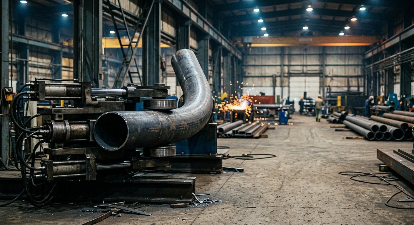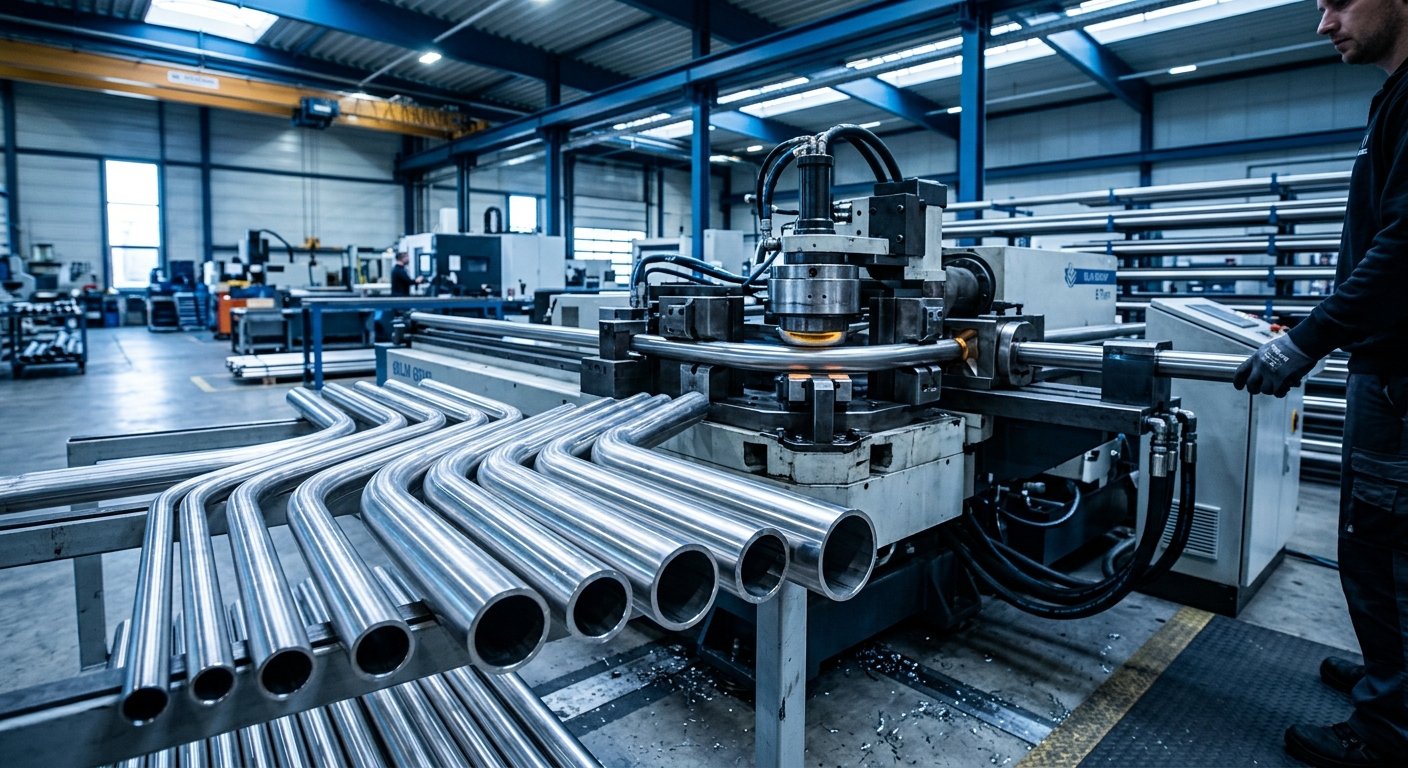
Ask any manufacturing engineer what separates a successful tube bending project from a costly scrap pile, and they’ll often point to the same factor: the relationship between a tube’s outer diameter and its wall thickness. This ratio—commonly called the OD-to-wall ratio or D/t ratio—governs whether your bend will hold tolerances, maintain flow characteristics, or collapse under the tooling pressure. Understanding it isn’t optional for precision tube bending applications. It’s foundational.
This guide breaks down how OD-to-wall ratios affect bending behavior, what thresholds matter for demanding industries like aerospace and oil & gas, and how the right equipment and tooling strategy keep your production on spec.
What Is the OD-to-Wall Ratio?
The OD-to-wall ratio (D/t) is calculated by dividing the tube’s outer diameter by its wall thickness. A 2-inch OD tube with a 0.065-inch wall yields a D/t of approximately 30.8. That number carries significant weight in the bending process.
In general terms:
- Low D/t (under 10): Thick-walled tube—more resistant to collapse, but requires higher bending forces and more robust tooling.
- Moderate D/t (10–20): Standard range for many industrial applications; manageable with proper mandrel support.
- High D/t (20–50+): Thin-walled tube—significantly more prone to ovality, wrinkling, and wall thinning on the extrados.
The higher the ratio, the more challenging the bend. Thin-walled tubes in aerospace applications routinely push D/t ratios above 30, demanding precision equipment, experienced operators, and carefully engineered tooling packages.
Why the Ratio Matters in Precision Bending
During any tube bend, the material on the outside of the bend (extrados) is placed in tension and experiences wall thinning, while the inside (intrados) is placed in compression and is prone to wrinkling or buckling. The severity of both effects scales directly with the D/t ratio.
High-ratio tubes—think aerospace hydraulic lines or thin-wall instrumentation tubing—offer very little structural resistance to these forces. Without adequate mandrel support, the tube can collapse or ovalize, compromising cross-sectional area and defeating the purpose of the bend entirely. In systems where fluid flow, pressure ratings, or structural integrity are critical, even minor ovality becomes a rejection criterion.
The ASTM International publishes material standards that define acceptable dimensional tolerances for tube products across alloys and grades—standards that directly inform how tight a D/t ratio a given material can sustain during bending operations.
Mandrel Selection and the D/t Relationship
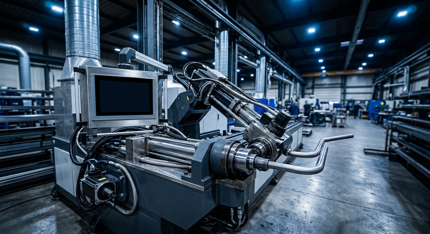
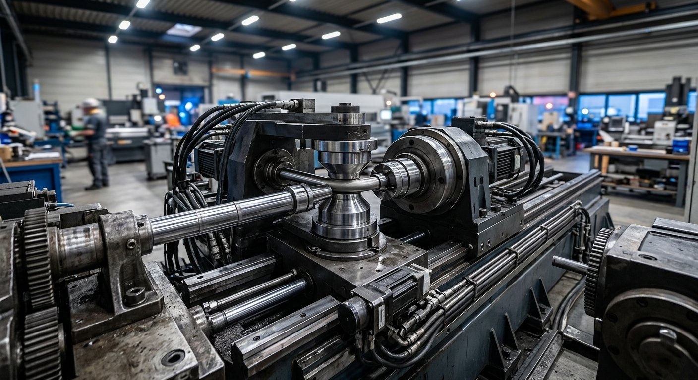
Mandrel bending machines exist precisely to address the challenges posed by high D/t ratios. A mandrel—inserted inside the tube during the bend—provides internal support that prevents collapse and controls wall thinning. But not all mandrels are created equal, and the right selection depends heavily on your D/t ratio.
Types of Mandrels and Their Applications
- Plug mandrel: Provides basic support near the bend tangent; suitable for low-to-moderate D/t ratios with generous bend radii.
- Ball mandrel (single or multi-ball): Follows the bend contour with articulating balls; essential for high D/t thin-wall applications where ovality control is critical.
- Sand-filled or internal pressure mandrels: Used in specialized applications where conventional tooling is impractical.
As a rule of thumb, thin-wall tubes with D/t ratios above 20 typically require a ball mandrel with the ball positioned precisely at the bend tangent. Too far forward causes marks on the tube interior; too far back allows the unsupported section to collapse. Getting this positioning right is a function of both machine accuracy and operator knowledge—two areas where CNC tube benders with programmable mandrel positioning provide a measurable advantage over manually controlled equipment.
Bend Radius and Its Interaction with D/t
OD-to-wall ratio doesn’t operate in isolation. It interacts critically with the centerline bend radius (CLR), typically expressed as a multiple of the OD—1D, 2D, 3D, and so on. Tighter bend radii amplify the stresses created by high D/t ratios.
A tube with a D/t of 25 bent to a 2D centerline radius faces far more demanding conditions than the same tube bent to a 5D radius. When projects require tight-radius bends on thin-wall tubing—common in aerospace tube bending and compact hydraulic assemblies—the combination demands premium tooling, precise lubrication, and machines capable of holding position tolerances within fractions of a degree.
The NASA Technical Reports Server documents numerous case studies involving aerospace tube assemblies where CLR-to-OD ratios and wall specifications are engineered simultaneously to meet both structural and weight requirements—a useful reference for engineers working in similar high-stakes environments.
Material Considerations at Different D/t Ratios
Material choice significantly affects how a tube responds at a given D/t ratio. Yield strength, elongation, and work-hardening behavior all factor into bending outcomes.
Stainless Steel
High work-hardening rates make stainless steel more challenging at elevated D/t ratios. Springback is pronounced, requiring overbend compensation. CNC tube benders with springback compensation algorithms are strongly preferred for stainless production runs where dimensional repeatability is non-negotiable.
Titanium
Titanium’s high strength-to-weight ratio and limited ductility make it one of the most demanding materials for precision tube bending. Thin-wall titanium—common in aerospace—requires heated tooling in some cases, controlled bending speeds, and precise D/t management to avoid cracking at the extrados.
Carbon and Alloy Steel
More forgiving than titanium or high-nickel alloys, carbon steel still exhibits wall thinning and wrinkling at high D/t ratios, particularly in oil & gas and petrochemical applications where schedule pipe bending may involve heavy wall sections on one project and thin-wall instrumentation tubing on the next.
Aluminum
Aluminum’s relatively low yield strength means thin-wall aluminum tubing at high D/t ratios can distort easily. Heat-treated alloys like 7075 are particularly sensitive and may require specific tooling geometry to maintain cross-sectional integrity.
Tube Bending Technology: Equipment Capabilities Matter
Understanding D/t ratios is only half the equation. Producing accurate bends at challenging ratios requires tube bending technology capable of maintaining tight control over every variable—bend angle, mandrel position, clamp pressure, and wiper die placement.
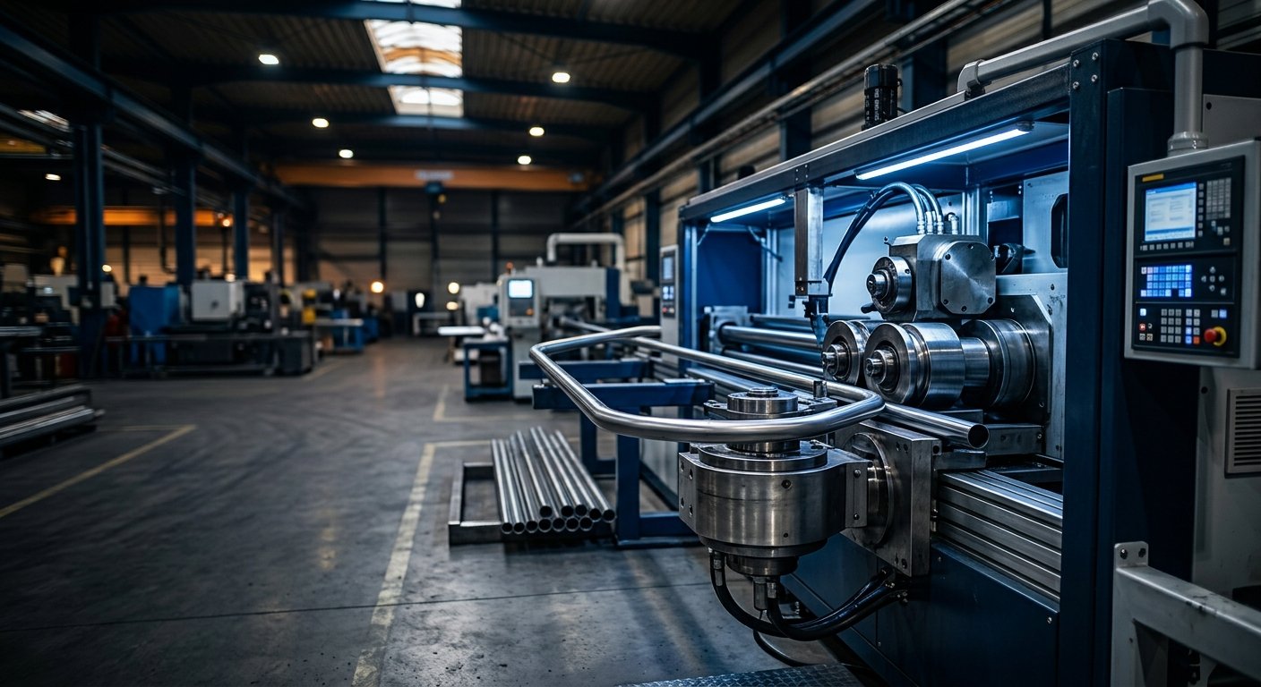
Modern CNC tube benders allow engineers to program exact bend parameters, store tooling setups for repeatable production, and compensate for springback automatically. For high-D/t thin-wall applications, this level of control isn’t a luxury—it’s a requirement. Machines designed for precision aerospace tube bending incorporate features such as:
- Programmable mandrel retract timing to prevent marking
- Pressure die assist to reduce drag and wall thinning
- Multi-stack tooling heads for complex multi-radius assemblies
- Real-time angle verification and closed-loop correction
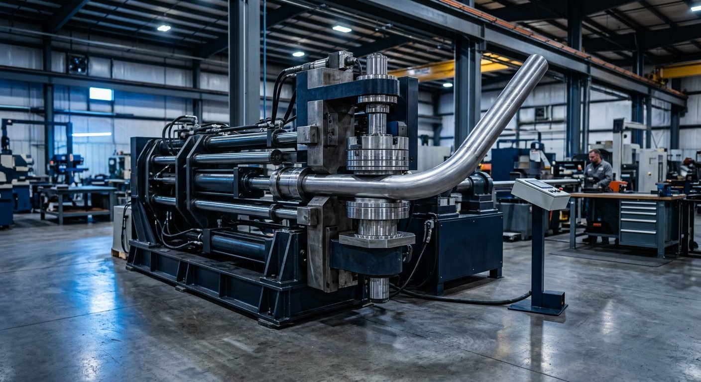
For manufacturers working across a range of tube sizes and D/t ratios, a platform that supports both mandrel bending machines and larger pipe bending machines from the same controls environment reduces operator training burden and improves cross-project consistency. Learn more about production-grade solutions at Hines tube bending machines and pipe bending machines.
Practical D/t Limits by Application
While no universal cutoff applies to every material and bend radius combination, the following general thresholds provide a useful starting framework:
- Aerospace hydraulic and pneumatic lines: D/t ratios of 20–40 are common; ball mandrel bending with wiper dies is standard.
- Oil & gas process piping: Typically lower D/t ratios (under 20) due to heavier wall requirements; mandrel bending may be supplemented with hot bending for large diameters.
- Petrochemical instrumentation tubing: Thin-wall, high-D/t applications requiring tight ovality control and surface finish preservation.
- Defense and military assemblies: Strict specification compliance often governs D/t requirements, with MIL-SPEC documentation driving tooling and process parameters.
For a deeper look at aerospace-specific bending requirements, visit Hines aerospace tube bending resources, where application-specific guidance addresses the material and geometric challenges common in aircraft and spacecraft manufacturing.
Frequently Asked Questions
What D/t ratio requires a mandrel for tube bending?
As a general guideline, D/t ratios above 10–12 typically benefit from mandrel support during bending. For ratios exceeding 20, a ball mandrel is usually required to prevent ovalization and wall collapse, especially at tighter bend radii.
How does OD-to-wall ratio affect wall thinning?
Higher D/t ratios produce more pronounced wall thinning on the extrados (outside of the bend). This thinning percentage increases as the bend radius tightens. Pressure die assist on CNC tube benders helps counteract this effect by applying forward axial force during the bend.
Can all materials be bent at the same D/t ratio?
No. Material ductility, yield strength, and work-hardening behavior all affect what D/t ratios are achievable. Titanium and high-strength stainless alloys have more restrictive practical limits than mild steel or aluminum, and may require specialized tooling, lubrication, or bending speeds.
What is springback and how does D/t ratio affect it?
Springback is the elastic recovery that occurs after a bend is completed, causing the angle to partially open. Higher-strength materials at high D/t ratios tend to exhibit more springback. CNC tube benders with programmable overbend compensation account for this systematically, reducing trial-and-error in setup.
How do I select the right tube bending machine for a high-D/t application?
Identify your maximum OD, minimum wall thickness, tightest bend radius, and target material. These parameters define your mandrel requirements, machine tonnage, and control sophistication. Working with an experienced bending equipment manufacturer—one with application-specific engineering support—is the most reliable path to specifying the right solution for demanding projects.
Partner with Proven Expertise
Managing OD-to-wall ratios across diverse materials and applications demands more than the right formula—it requires equipment engineered for precision, tooling selected by experienced application engineers, and the support structure to keep production running. With 50 years of tube and pipe bending expertise and a track record serving NASA and military clients, Hines Bending Systems brings the technical depth to help you navigate even the most demanding D/t challenges.
Whether you’re specifying a CNC tube bender for aerospace production or configuring a mandrel bending machine for oil & gas instrumentation tubing, our team is ready to work through the details with you. Contact Hines Bending Systems today to discuss your application requirements and find the precision solution your project demands.

About Hines Bending Systems
Hines Bending Systems is a leading American manufacturer of precision tube and pipe bending equipment serving aerospace, energy, oil & gas, petrochemical, and defense industries. With 50 years of proven expertise and a track record of supplying NASA and military clients, Hines delivers custom bending solutions for demanding applications ranging from high-volume production to specialized one-off projects. The company combines deep technical knowledge with comprehensive support including training and service, positioning itself as a partner in customer success rather than just an equipment supplier. Visit hinesbending.com →